
Fan, bearing and sleeve thereof

a technology of a fan and a sleeve, which is applied in the direction of positive displacement liquid engines, piston pumps, liquid fuel engines, etc., can solve the problems of shortening the life of the bearing b>10/b>, affecting the performance of the bearing, so as to reduce the up and down vibration of the bearing, the effect of reducing the consumption and volatilization of lubrication fluid and reducing the bearing

Inactive Publication Date: 2011-04-07
HSU WEI CHUN +2
View PDF13 Cites 1 Cited by
  • Summary
  • Abstract
  • Description
  • Claims
  • Application Information

AI Technical Summary

Benefits of technology

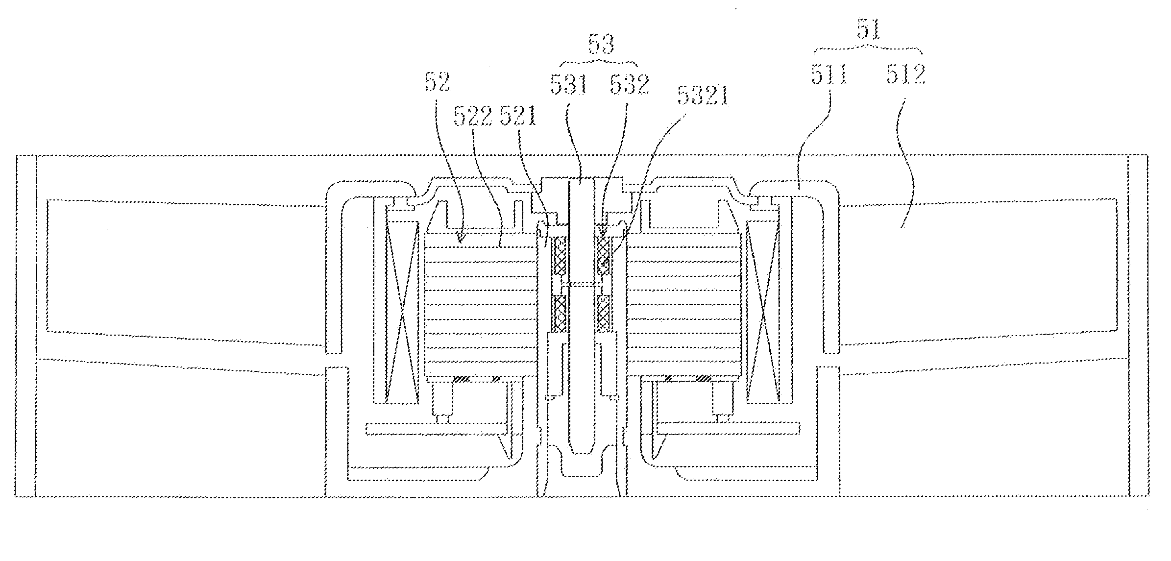
"The invention is a bearing structure that reduces lubrication fluid consumption and volatilization, and provides a circulating lubrication loop to reduce friction between a sleeve and a bearing, thereby lengthening the lifetime of the bearing. The bearing has an axial hole and a plurality of first grooves formed on an inner surface of the axial hole and extending to a top surface of the bearing. The invention also includes a fan with an impeller, stator structure, and rotor structure, where the bearing is used in conjunction with a shaft and sleeve, and the bearing is constituted by the axial hole, first grooves, chamfers, and cut side. The first grooves, chamfers, and cut side can mix the oil gas of the lubrication fluid sufficiently, to form a circulating lubrication loop and to generate oil gas hydrodynamic pressure on the top surface and the periphery of the bearing, without using the conventional resisting washer. The invention forms the circulating loop of the lubrication fluid in the closed chamber, reducing consumption and volatilization, lengthening the lifetime of the bearing, and decreasing manufacturing cost because the machining precision of the hearing does not have to be very high."

Problems solved by technology

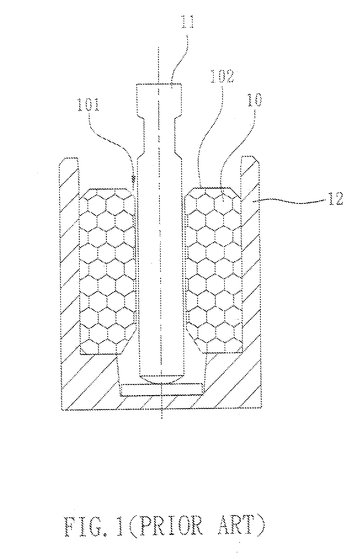
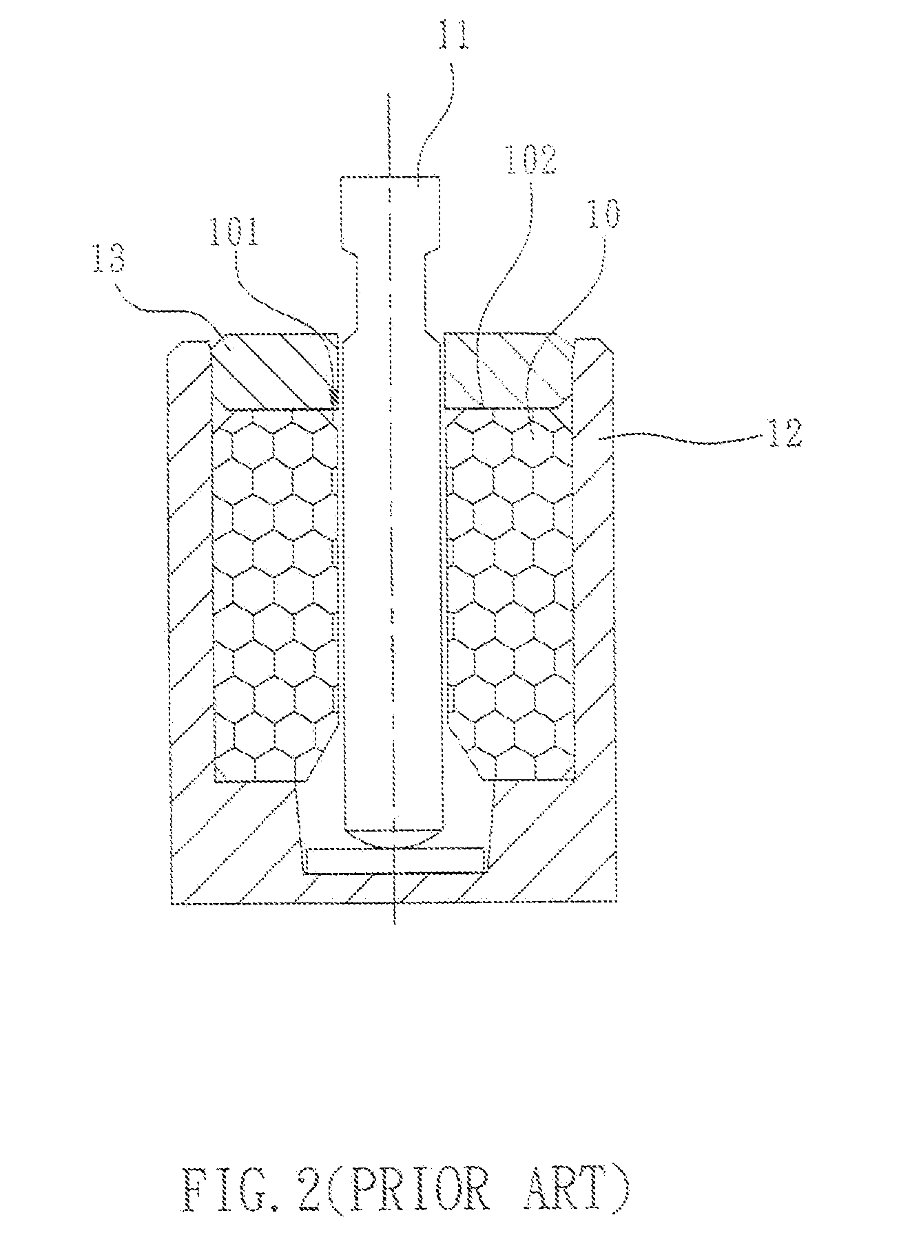
More particularly, when the bearing 10 is placed upended, such leakage become more serious that the lifetime of the bearing 10 is shortened, or the overall operation becomes rough due to insufficient lubrication oil and the resultant excessive frictional force between the bearing and the shaft 11 or the sleeve 12.
However, the effect is limited because the lubrication oil may still leak to the outside through the gap between the bearing 10 and the shaft 11 and the gap between the bearing 10 and the sleeve 12.

Method used


Image

  • Fan, bearing and sleeve thereof
  • Fan, bearing and sleeve thereof
  • Fan, bearing and sleeve thereof

Examples


Embodiment Construction

[0022]The present invention will be apparent from the following detailed description, which proceeds with reference to the accompanying drawings, wherein the same references relate to the same elements.

[0023]Referring to FIG. 3, a bearing 1 according to the embodiment of the invention includes an axial hole 11 and a plurality of first grooves 12. In this embodiment, the first grooves 12 are disposed on an inner surface 111 of the axial hole 11 and extend to a top surface 13 of the hearing 1. The first grooves 12 extend in a direction parallel to the axial direction of the axial hole 11, or extend helically (not shown) on the inner surface 111 of the axial hole 11.

[0024]A plurality of second grooves 15 can be formed on a periphery 14 of the bearing 1. The second grooves 15 respectively correspond to the first grooves 12, or are correspondingly formed between the first grooves 12 (not shown). When the hearing 1 is rotating, the lubrication fluid flows up to the top surface 13 of the h...


PUM


Abstract

A bearing includes an axial hole and a plurality of first grooves. The first grooves are formed on the inner wall of the bearing, and extends through the top surface and to the outer wall of the bearing. The lubricant oil originally held in the bearing can be guided to flow around the whole bearing effectively.

Description

CROSS REFERENCE TO RELATED APPLICATIONS[0001]This is a Continuation application of U.S. patent application Ser. No. 11 / 709,266 filed Feb. 22, 2007, which is a non-provisional application which claims priority under 35 U.S.C. §119(a) on Patent Application No(s). 095111465 filed in Taiwan, Republic of China on Mar. 31, 2006. the entire contents of which are hereby incorporated by reference.BACKGROUND OF THE INVENTION[0002]1. Field of Invention[0003]The invention relates to a fan, a bearing and a sleeve thereof, and in particular, to a fan, a bearing and a sleeve thereof with reduced consumption and volatilization of lubrication fluid.[0004]2. Related Art[0005]Motors have been widely used in vehicles, fans, pumps and computer peripherals, such as printers and scanners, and the bearing structure of a motor directly influences the quality of the motor. In order to enhance the self-lubrication of the bearing and prevent impact, a hearing is usually adopted. The conventional bearing is mad...

Claims


Application Information

Patent Timeline
Patent Type & Authority Applications(United States)
IPC IPC(8): F01D25/16F16C33/10
CPCF04D29/057F04D29/063F16C17/02F04D25/0626F16C33/107F04D25/062F16C33/103
Inventor HSU, WEI-CHUNCHANG, SHUN-CHENHUANG, WEN-SHI
Owner HSU WEI CHUN
Learn More