Cable connector having cross-talk suppressing feature and method for making the connector

a technology of cross-talk and connector, which is applied in the direction of coupling device connection, coupling protective earth/shielding arrangement, electrical equipment, etc., can solve the problems of inability to access information from the internet at the speed as quickly as expected, the information processing speed of the i/o port device of the machine is still relatively low, and the machine cannot achieve the speed of the internet with a speed as fast as expected, so as to achieve high speed, effectively reduce and suppress

Inactive Publication Date: 2005-03-22
HON HAI PRECISION IND CO LTD
View PDF4 Cites 53 Cited by
  • Summary
  • Abstract
  • Description
  • Claims
  • Application Information

AI Technical Summary

Benefits of technology

Accordingly, an object of the present invention is to provide a high speed cable connector wherein cross-talk between neighboring signal pairs at an end of a cable connecting with the connector can be effectively reduced and suppressed.

Problems solved by technology

Following the popularity of the Internet, information access speed becomes an important issue.
Although the information processing speed of a central process unit (CPU) of a data processing machine, i.e., a computer or a server, is increased enormously, information processing speed of I / O port devices of the machine is still relatively low, which results in that information still can not be accessed by the machine from the Internet with a speed as quickly as expected.
An electrical connector for use in such high speed application always confronts a problem of cross-talk.
The structure disclosed by the '839 patent still cannot overcome the problem of cross-talk occurred in an electrical connector for InfiniBand™ architecture since it must transmit and process information and data at an even higher speed.
Furthermore, it is unreliable regarding the electrical connection between the ground lines 38 and the ground contacts 26 since they are not directly connected together but via an arrangement member 16.

Method used


Image

  • Cable connector having cross-talk suppressing feature and method for making the connector
  • Cable connector having cross-talk suppressing feature and method for making the connector
  • Cable connector having cross-talk suppressing feature and method for making the connector

Examples


Embodiment Construction

Reference will now be made to the drawing figures to describe the present invention in detail.

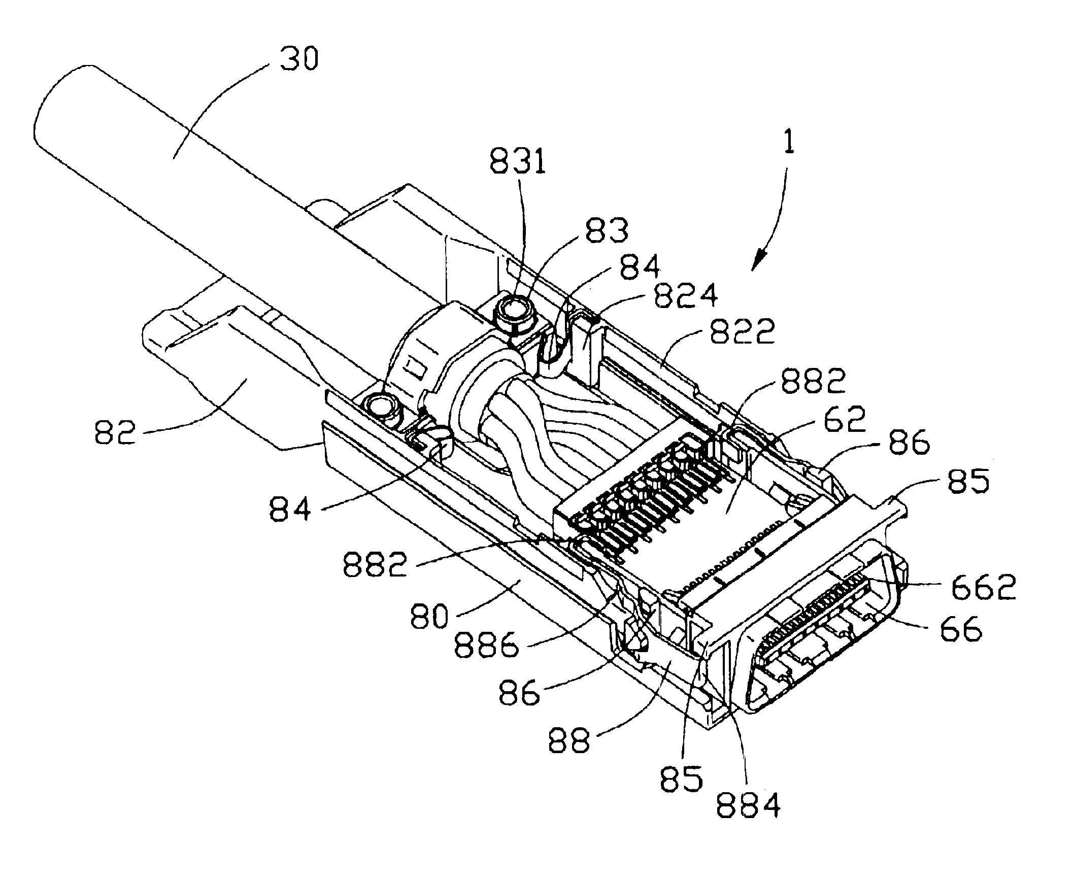
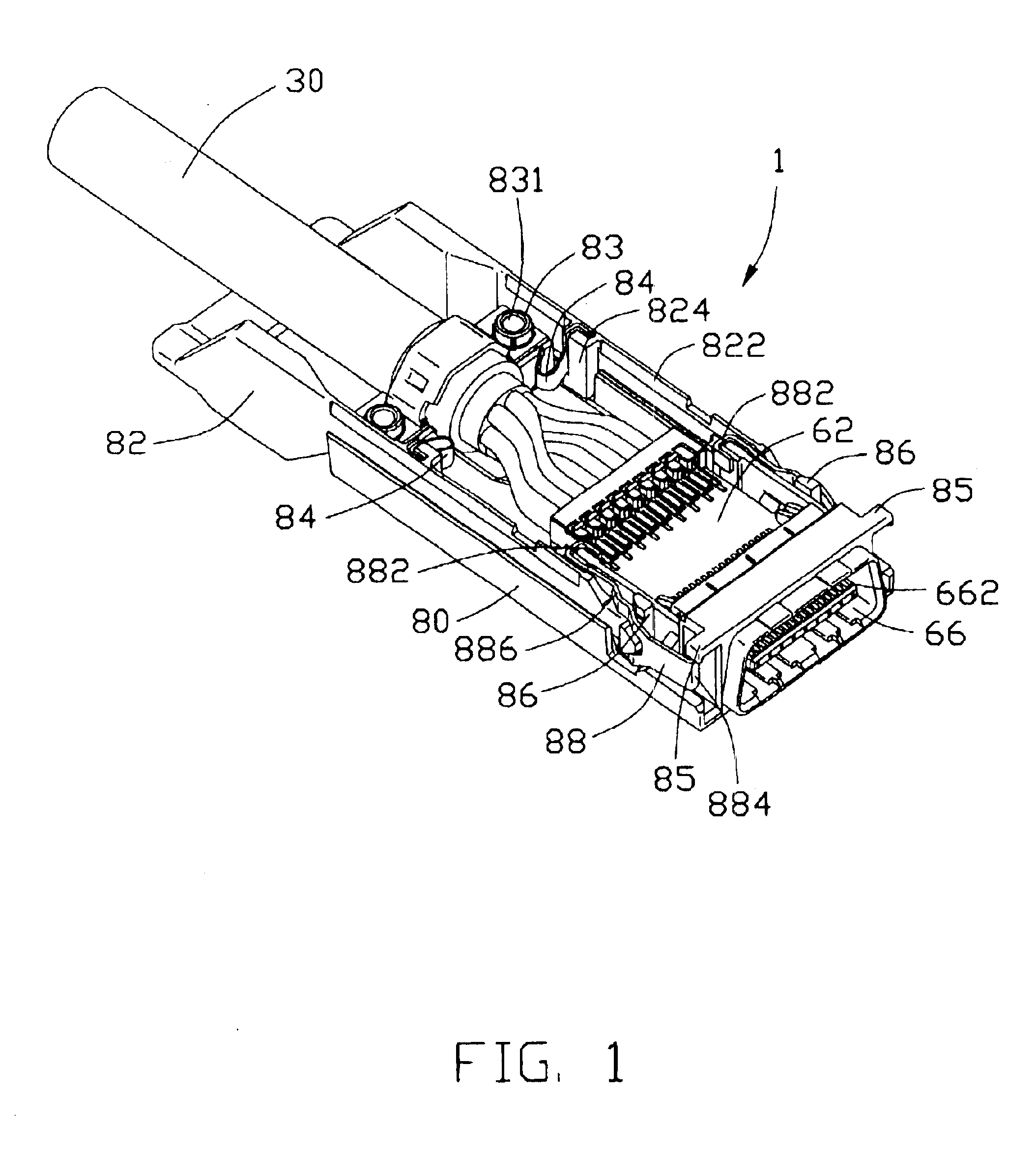
Referring to FIGS. 1 and 2, a cable connector 1 for use in an InfiniBand™ application in accordance the present invention comprises a cover 3 (FIGS. 4, 7 and 8), a cable assembly 30 and a base 80. Both the cover 3 and base 80 are formed by die casting of metal such as aluminum alloy. The cover 3 is provided with screws (not shown) for screwing into screw holes 831 defined in studs 83 formed in the base 80 after the cable assembly 30 is put in the base 80 to thereby assemble the cover 3, the cable assembly 30 and the base 80 together. To mount the cover 3 to the base 80, firstly protrusions (not shown) formed on a front end of the cover 3 are positioned below side flanges 85 formed on a front end of the base 80, respectively. Then a rear end of the cover 3 on which the screws are located is pivoted downwardly about the flanges 85 toward the base 80 until the rear end of the cover 3 is in con...


PUM


Abstract

A high speed cable connector (1) includes a cover (3), a base (80) and a cable assembly (30) mounted between the cover and the base. The cable assembly includes a cable (42) consisting of a plurality of lines (44). Each line has a pair of upper and lower signal wires (442, 444) and a grounding wire (446). Front ends of the lines are sandwiched between upper half (462) and lower half (464) of a spacer (46) to which upper and lower shielding plates (50, 52) are respectively mounted. The upper and lower shielding plates are electrically connected with each other. The upper and lower signal wires are soldered to signal circuitry on top and bottom faces of a printed circuit board (62), respectively. The upper and lower shielding plates have engaging arms (508) soldered to ground circuitry of on the top and bottom faces of the printed circuit board, respectively. Each grounding wire is soldered to a corresponding upper shielding plate. Each pair of upper and lower signal wires is located between two pairs of upper and lower shielding plates, whereby cross-talk between the signal wires of two neighboring lines can be effectively suppressed.

Description

BACKGROUND OF THE INVENTION1. Field of the InventionThe present invention relates to a cable connector, and particularly to a high speed cable connector for use in InfiniBand™ application.2. Description of Related ArtFollowing the popularity of the Internet, information access speed becomes an important issue. Although the information processing speed of a central process unit (CPU) of a data processing machine, i.e., a computer or a server, is increased enormously, information processing speed of I / O port devices of the machine is still relatively low, which results in that information still can not be accessed by the machine from the Internet with a speed as quickly as expected.To solve this problem, an InfiniBand™ I / O port structure is proposed, which offers three levels of link performance —2.5 Gbits, 10 Gbits and 30 Gbits / sec. An electrical connector for use in such high speed application always confronts a problem of cross-talk. Cross-talk means interference of signals of neig...

Claims


Application Information

Patent Timeline
Patent Type & Authority Patents(United States)
IPC IPC(8): H01R13/658H01R13/66
CPCH01R12/62H01R13/65807H01R13/6593H01R13/6471H01R13/6589H01R12/775H01R13/6658
Inventor WU, JERRY
Owner HON HAI PRECISION IND CO LTD
Why Eureka
Try Eureka