Damper mechanism and high pressure fuel pump

a technology of damper mechanism and fuel pump, which is applied in the direction of fuel injecting pump, machine/engine, positive displacement liquid engine, etc., can solve the problems of large welding space, increase in the size of damper mechanism or high pressure fuel pump, etc., and achieve the effect of reducing fuel pressure pulsation and fuel pressure pulsation

Active Publication Date: 2006-10-24
HITACHI ASTEMO LTD
View PDF12 Cites 58 Cited by
  • Summary
  • Abstract
  • Description
  • Claims
  • Application Information

AI Technical Summary

Benefits of technology

[0004]As mentioned above, the prior art uses a single metal diaphragm, and thus the diameter of the metal diaphragm must be increased to sufficiently reduce pressure pulsation. If two single metal diaphragm dampers are used for the high pressure fuel pump, the fuel pressure pulsation may be reduced without increase in diameter. However, according to such a way, since the plural peripheral portions of the diaphragms are secured in the housing by welding, a large space is required for welding. This results in increase in the size of the damper mechanism or high pressure fuel pump.
[0005]The object of the present invention is to provide a small-sized damper mechanism highly effective in the reduction of fuel pressure pulsation or a small-sized high pressure fuel pump provided with the damper mechanism highly effective in the reduction of fuel pressure pulsation.

Problems solved by technology

However, according to such a way, since the plural peripheral portions of the diaphragms are secured in the housing by welding, a large space is required for welding.
This results in increase in the size of the damper mechanism or high pressure fuel pump.

Method used


Image

  • Damper mechanism and high pressure fuel pump
  • Damper mechanism and high pressure fuel pump
  • Damper mechanism and high pressure fuel pump

Examples


first embodiment

[0022](First Embodiment)

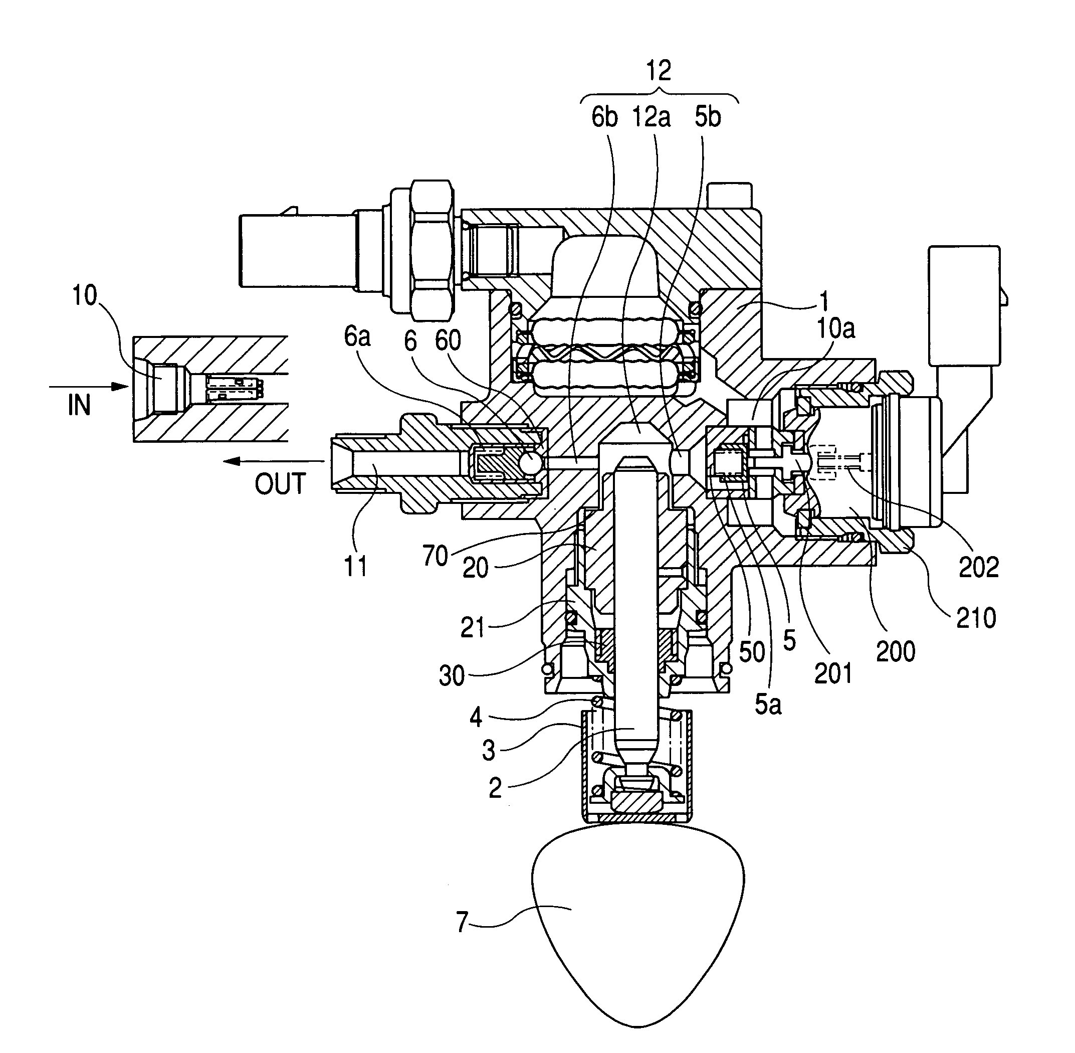
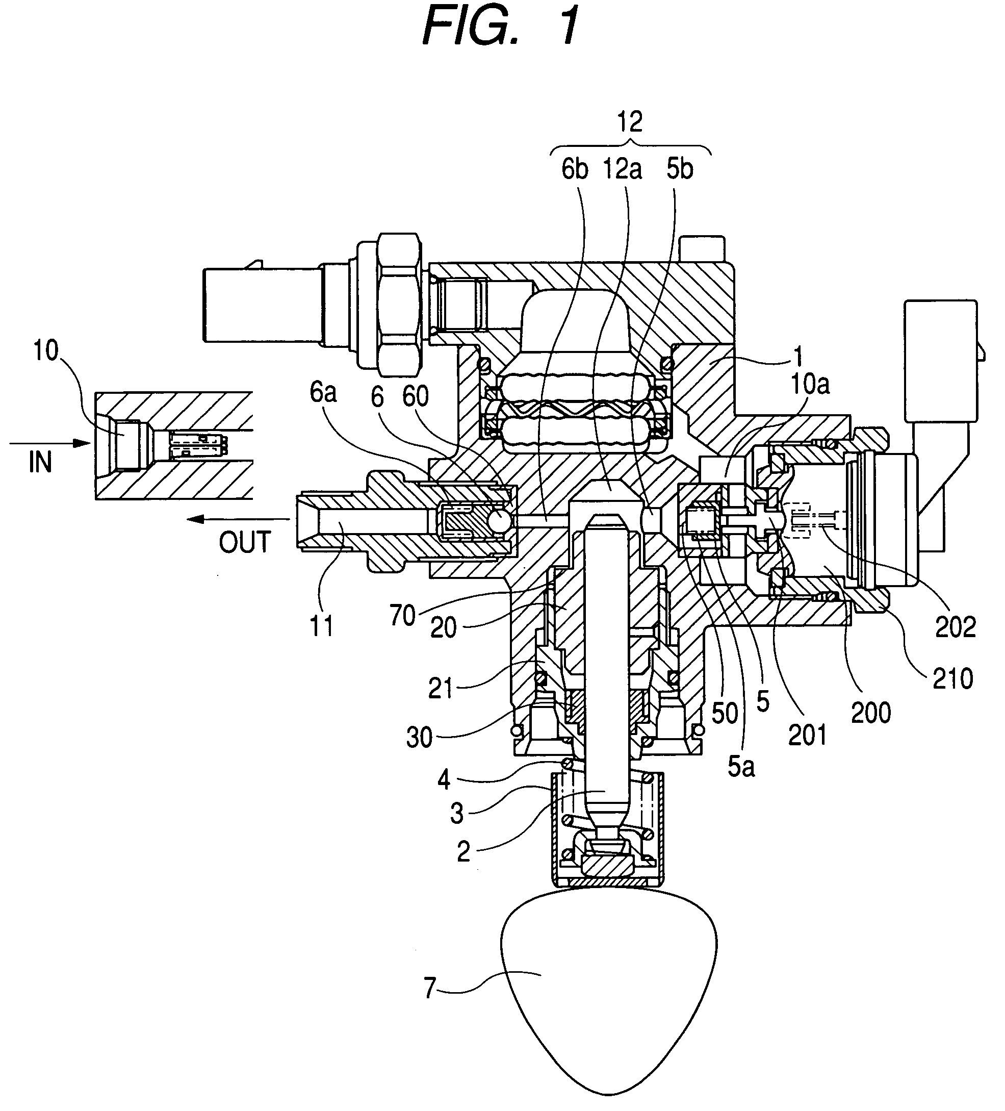
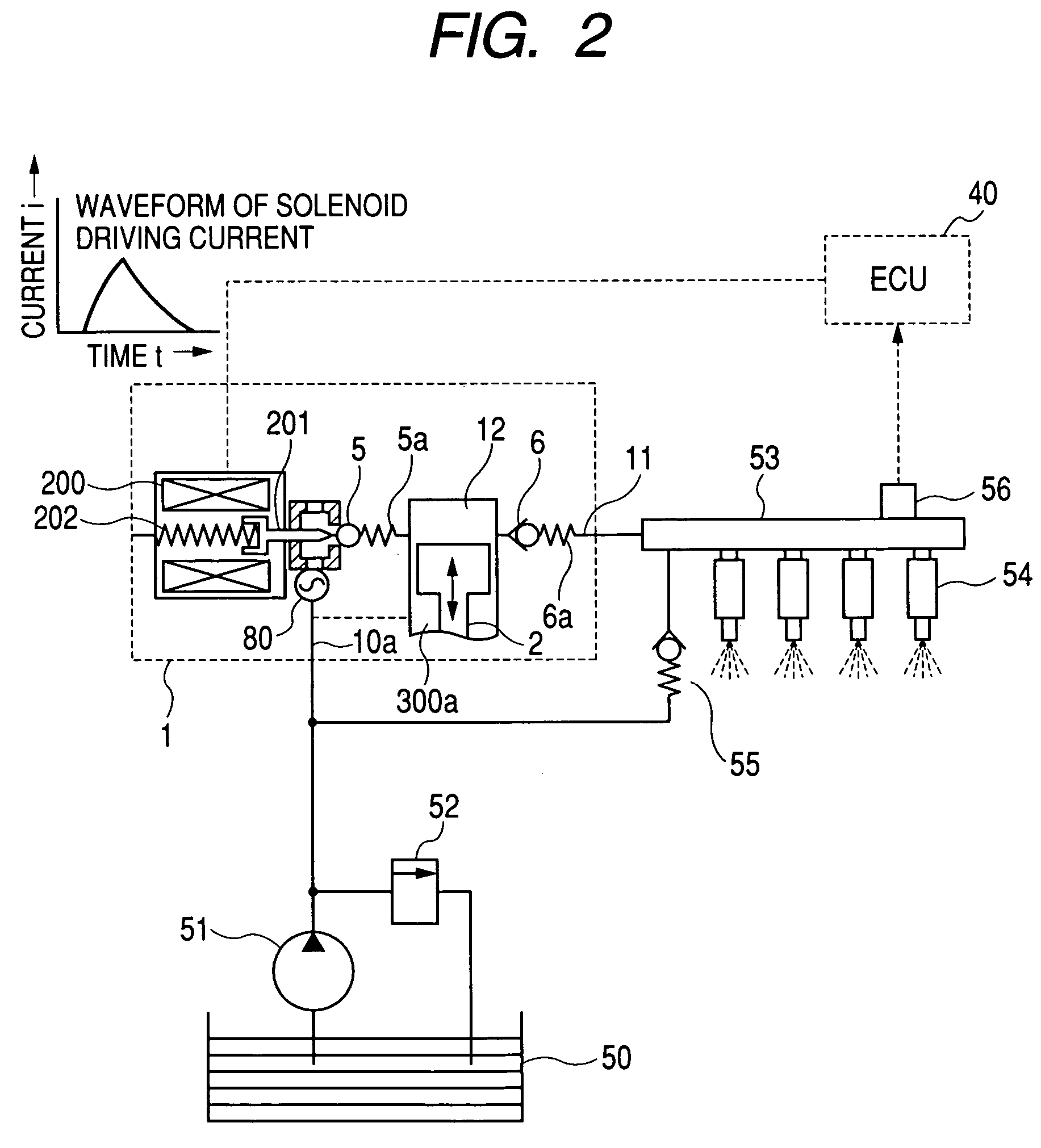
[0023]FIG. 1 is a longitudinal sectional view illustrating the whole of a high pressure fuel pump to which the present invention is applied. FIG. 2 is an overall system diagram illustrating a fuel supply system for internal combustion engine. The figure illustrates a high pressure fuel supply system for use in a direct injection type (cylinder injection type) internal combustion engine.

[0024]An intake joint 10 which forms a fuel intake port and a delivery joint 11 which forms a fuel delivery port are screwed to the main body of the pump (also referred to as “pump body”) 1. A pressure chamber 12 for pressurizing fuel is formed at a fuel passage between the intake joint 10 and the delivery joint 11.

[0025]An intake valve 5 is provided at the inlet of the pressure chamber 12, and a delivery valve 6 is provided at the delivery joint 11. The intake valve 5 and the delivery valve 6 are respectively energized by springs 5a and 6a in such a direction as to close the i...

second embodiment

[0052](Second Embodiment)

[0053]Next, another embodiment of the present invention will be described referring to FIG. 4.

[0054]In this embodiment, as a mechanism for reducing fuel pressure pulsation, two double metal diaphragm dampers 80 and 81 are provided at a fuel passage between the intake joint 10 and the intake chamber (low pressure chamber) 10a.

[0055]The double metal diaphragm damper 80 has its rim clamped between the washer 103 and the washer guide 102 over the entire circumference like the first embodiment. The washer 103 is provided with the same chamfers on the outer diameter sides of its both sides. The washer 103 is machined so that its diameter is same as the diameter of the rim of the double metal diaphragm damper 80. The washer guide 102 is provided with an annular groove 102a. The fuel chambers 10b and 10c are connected to the fuel chamber (intake chamber) 10a.

[0056]The double metal diaphragm damper 81 has the rim clamped between the washer 103 and the damper cover ...

third embodiment

[0062](Third Embodiment)

[0063]Next, a further embodiment of the present invention will be described referring to FIG. 5.

[0064]As a mechanism to reduce fuel pressure pulsation, two double metal diaphragm dampers 80 and 81 are provided between the fuel passage 10 and the low pressure chamber 10a. The metal diaphragm dampers 80 and 81 are different from each other in cross-sectional shape.

[0065]The two double metal diaphragm dampers 80 and 81 have their rims clamped between each washer 103 and each washer guide 102 over the entire circumference. The washers 103 are provided with the same chamfers on the outer diameter sides of its both sides. The rims of the washers 103 are machined to the same dimensions as the rims of the double metal diaphragm dampers 80 and 81. The washer guides 102 are provided with each annular groove 102a. Further, the fuel chambers 10b, 10c, and 10d are connected to the fuel chamber (intake chamber) 10a.

[0066]A spring 104 is provided between the two washers 10...


PUM


Abstract

To obtain a small and high performance damper mechanism which reduces pressure pulsation in low pressure-side fuel in the high pressure fuel pump in a high pressure fuel supply system or a high pressure fuel pump provided with the small and high performance damper mechanism.Two metal diaphragms are welded together over the entire circumference to obtain a metal diaphragm assembly (also referred to as “double metal diaphragm damper”). The whole or part of the portion of the metal diaphragm assembly other than the weld (for example, the portion inside the weld) is clamped by a pressing member and thereby the assembly is secured in a housing enclosure. The housing enclosure may be formed integrally with the body of a high pressure pump.

Description

CLAIM OF PRIORITY[0001]The present application claims priority from Japanese application serial no. 2003-199946, filed on Jul. 22, 2003) the content of which is hereby incorporated by reference into this application.FIELD OF THE INVENTION[0002]The present invention relates to a damper mechanism for reducing fuel pressure pulsation in a high pressure fuel pump which supplies pressurized fuel to the fuel injection valves of an internal combustion engine. It also relates to a high pressure fuel pump provided with such a damper mechanism.BACKGROUND OF THE INVENTION[0003]As this type of damper mechanism or a high pressure fuel pump provided with the damper mechanism, various dumpers and pumps have been conventionally known. One example is a single metal diaphragm damper and a high pressure fuel pump provided with the single metal diaphragm damper. The single metal diaphragm damper is so constituted that the peripheral portion of a single metal diaphragm is secured in a housing by welding...

Claims


Application Information

Patent Timeline
Patent Type & Authority Patents(United States)
IPC IPC(8): F02M55/04F02M37/04F02M59/44F02M59/36F02M63/00F02M63/02F04B11/00
CPCF02M55/04F02M59/366F02M63/0225F02M63/024F02M63/028F04B11/0016F02M2200/24F02M2200/315
Inventor USUI, SATOSHIHASHIDA, MINORU
Owner HITACHI ASTEMO LTD
Why Eureka
Try Eureka