Low noise multiport connector

a multi-port connector, low noise technology, applied in the direction of printed circuit aspects, coupling device connections, printed capacitor incorporation, etc., can solve the problems of noise, noise is a major limitation factor in the performance of today's communication systems, and the transmission system adds distortion, etc., to reduce port to port crosstalk

Active Publication Date: 2007-12-20
ORTRONICS INC
View PDF76 Cites 61 Cited by
  • Summary
  • Abstract
  • Description
  • Claims
  • Application Information

AI Technical Summary

Benefits of technology

[0019]In an exemplary embodiment, an assembly is described wherein at least one BEMI and at least one coupling radiator are placed in each of regions (a), (b), (c), and (d). Placement of a BEMI and coupling radiator in each of the noise reducing regions is effective to reduce port to port crosstalk noise. An assembly of the present disclosure can include at least one balancing conductive substrate disposed in at least one of the noise reducing regions, the conductive substrate being in electrical communication with at least one of the coupling radiators disposed therein.
[0021]An exemplary method of the present disclosure is effective in reducing port to port crosstalk on a multiport assembly by placing at least one BEMI in at least one port to port noise compensation region of a PCB. The compensation signal(s) generated in the at least one compensation region is / are effective to substantially compensate for noise that results from port to port coupling. The BEMI is adapted to reduce port to port crosstalk noise by generating an opposite polarity signal relative to an unwanted noise signal. In an exemplary embodiment, at least one coupling radiator is disposed in at least one of the noise reducing regions and is electrically coupled to at least one of the electrical components of the plurality of ports. Another exemplary method according to the present disclosure provides or disposes at least one balancing conductive substrate in at least one of the noise reducing regions, such balancing conductive substrate being in electrical communication with at least one coupling radiator disposed in such noise reducing region.
[0022]Noise reducing regions of an exemplary method include: (i) region (a) generating noise compensation with respect to crosstalk noise that results from coupling between the modular insert terminals of one of the plurality of ports relative to IDC pins associated with an adjacent port; (ii) region (b) generating noise compensation with respect to crosstalk noise that results from coupling between modular insert terminals of a second of the plurality of ports relative to modular insert pins associated with an adjacent port; (iii) region (c) generating noise compensation with respect to crosstalk noise that results from coupling between modular insert terminals of a third of the plurality of ports relative to an IDC pins associated with an adjacent port; and (iv) region (d) generating noise compensation with respect to crosstalk noise that results from coupling between IDC pins associated with a fourth of the plurality of ports relative to IDC pins associated with another port. In an exemplary embodiment, at least one BEMI and at least one coupling radiator are placed in each of regions (a), (b), (c), and (d) so as to reduce port to port crosstalk noise through the generation of compensating signals.
[0024]The disclosed systems, assemblies and methods are effective in reducing port to port crosstalk by generating compensating signals in compensating regions defined on a PCB. In exemplary embodiments, four compensating regions are defined on the PCB, thereby generating compensating signals with respect to four distinct sources of crosstalk noise associated with the multiport assembly.

Problems solved by technology

The distortions are added by the transmission system, along with additional unwanted signals inserted somewhere between transmission and reception.
Noise is a major limiting factor in the performance of today's communication systems.
Problems that arise from noise include but are not limited to data errors, system malfunctions, and loss of desired signals.
Generally, crosstalk noise occurs when a signal from one source is coupled to another line.
NEXT increases the additive noise at the receiver and therefore degrades the signal-to-noise ratio (SNR).
However, coupling occurs as the signal travels through untwisted sections, such as plugs and plug contacts.
Although previously disclosed circuitry systems described above have been used to improve and / or compensate for internal crosstalk noise, they do not improve external crosstalk noise, such as ANEXT or AFEXT.

Method used


Image

  • Low noise multiport connector
  • Low noise multiport connector
  • Low noise multiport connector

Examples


Embodiment Construction

)

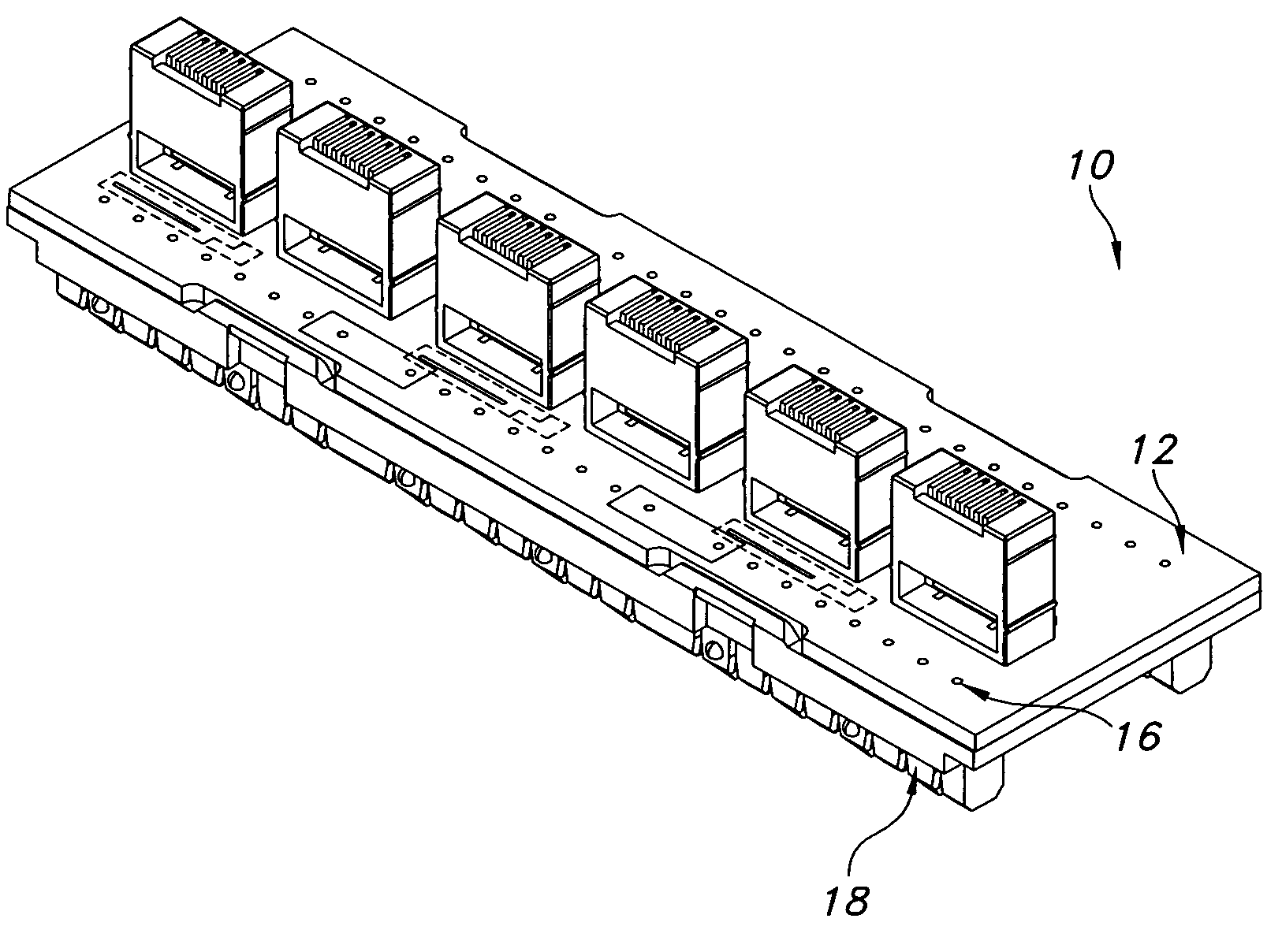
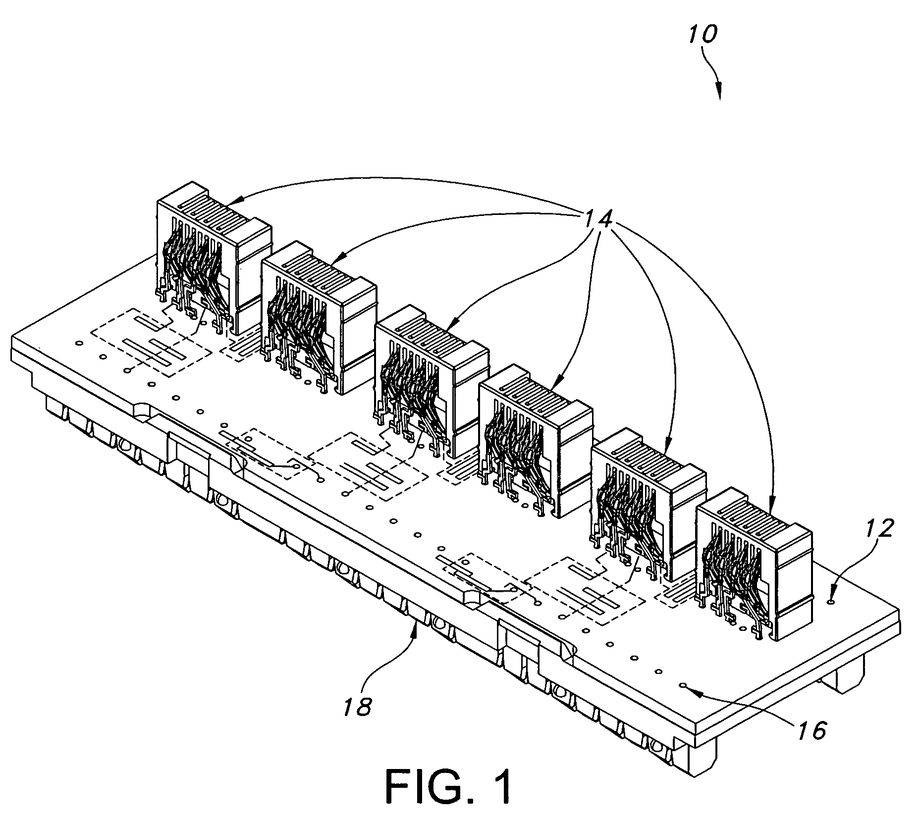
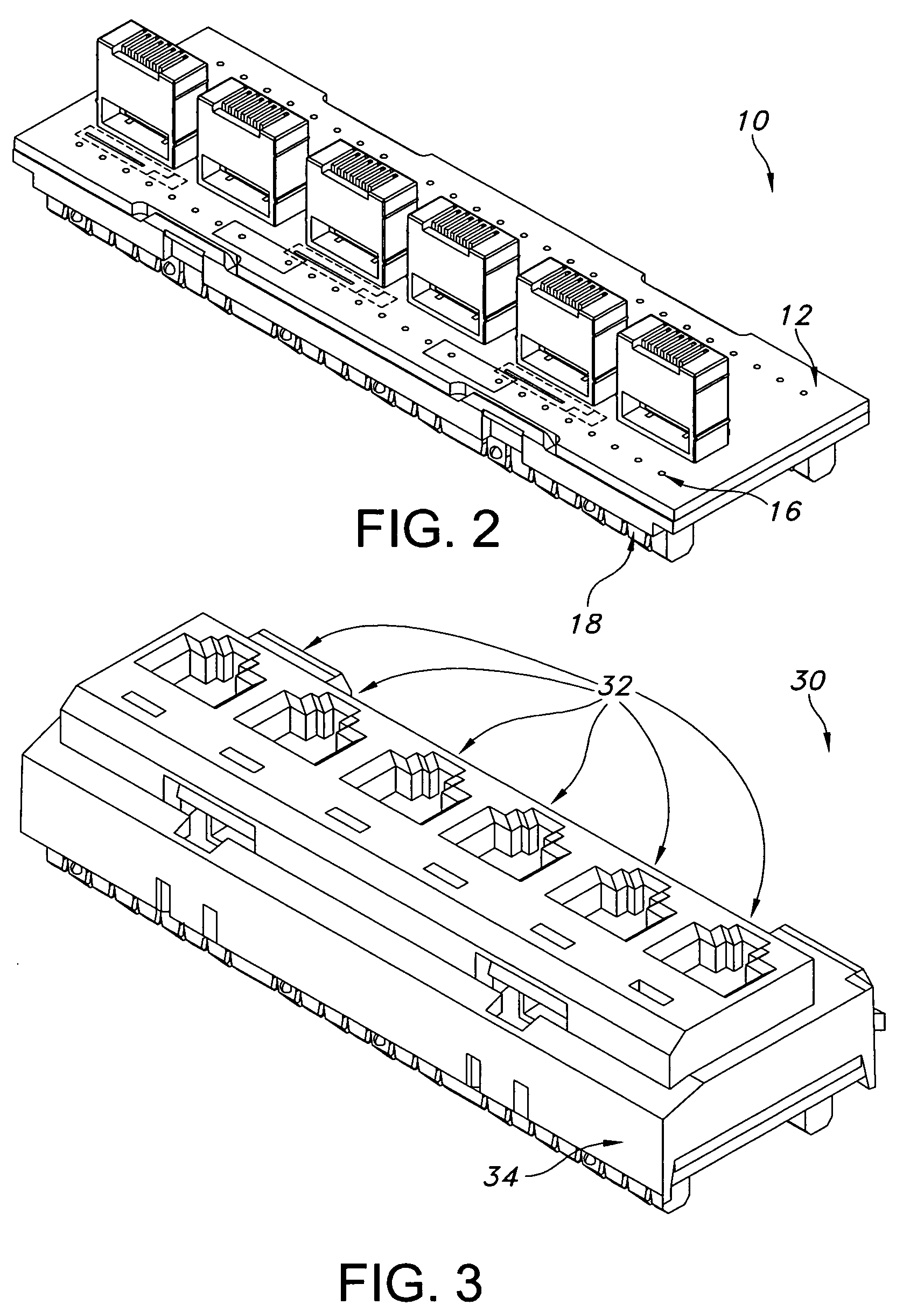
[0040]The present disclosure relates to connecting hardware adapted to be used in telecommunication systems to reduce port to port crosstalk noise and thereby improve the systems transmission of signals, including high speed data signals. In an exemplary embodiment, a connector, typically a multiport assembly, is described that reduces port to port crosstalk noise by utilizing a low signal radiated modular insert that is electrically connected to a PCB having a positive and negative combination compensation technique, without the need for shielding or additional physical components. Moreover, in an exemplary embodiment, an inexpensive, simple to manufacture and use connector / assembly is described that reduces port to port crosstalk noise between connector terminals.

[0041]A multiport connecting hardware of the present disclosure is typically characterized by: (a) a multiport assembly; (b) input interface connecting point(s) consisting of a matable plug that forms an electrical conne...


PUM


Abstract

The present disclosure is directed to systems and methods for a multiport connector assembly, used in telecommunication systems, that is designed to reduce electrical port to port crosstalk noise. The assembly is adapted to reduce noise from adjacent ports by placing balancing isolators and capacitor radiators in noise reducing regions of a printed circuit board. The signals are radiated in properly selected areas to rebalance the noise generated from adjacent transmission ports. By rebalancing noise inherently coupled by adjacency of transmitters, the port to port near-end crosstalk and far-end crosstalk noise is substantially reduced.

Description

BACKGROUND[0001]1. Technical Field[0002]The present disclosure relates to systems and methods that compensate for port to port crosstalk noise generated from electrical component proximity within a multiport assembly.[0003]2. Background Art[0004]Unshielded Twisted Pair (UTP) cable is a popular and widely used source of data transfer media because it is a very flexible and low cost media that can be used for either voice or data communications. In fact, UTP cable has rapidly become the de facto standard for Local Area Networks (LANs), in-building voice, and data communications applications. As UTP cabling continues to be an essential choice of media transmission, new and improved methods must be employed to meet the requirements of a transmitting data source. In an UTP, a pair of copper wires generally forms a twisted pair. For example, a pair of copper wires with diameters of 0.4-0.8 mm may be twisted together and wrapped with an insulated coating to form an UTP. The twisting of the...

Claims


Application Information

Patent Timeline
Patent Type & Authority Applications(United States)
IPC IPC(8): H01R24/00
CPCH01R13/6625H01R13/7195H05K1/0228H01R13/6466H05K2201/09236H05K2201/10189H05K1/162
Inventor AEKINS, ROBERT A.
Owner ORTRONICS INC
Why Eureka
Try Eureka