Suspension substrate, suspension, head suspension, hard disk drive and method for manufacturing suspension substrate
a technology of suspension substrate and head suspension, which is applied in the direction of maintaining head carrier alignment, recording information storage, instruments, etc., can solve the problems of increased cost, complex process, and insufficient supply of holes in the metal layer to adequately reduce transmission loss, so as to improve the production cost, the effect of significantly enhancing the electrical properties of the suspension substrate or the like devi
- Summary
- Abstract
- Description
- Claims
- Application Information
AI Technical Summary
Benefits of technology
Problems solved by technology
Method used
Image
Examples
first embodiment
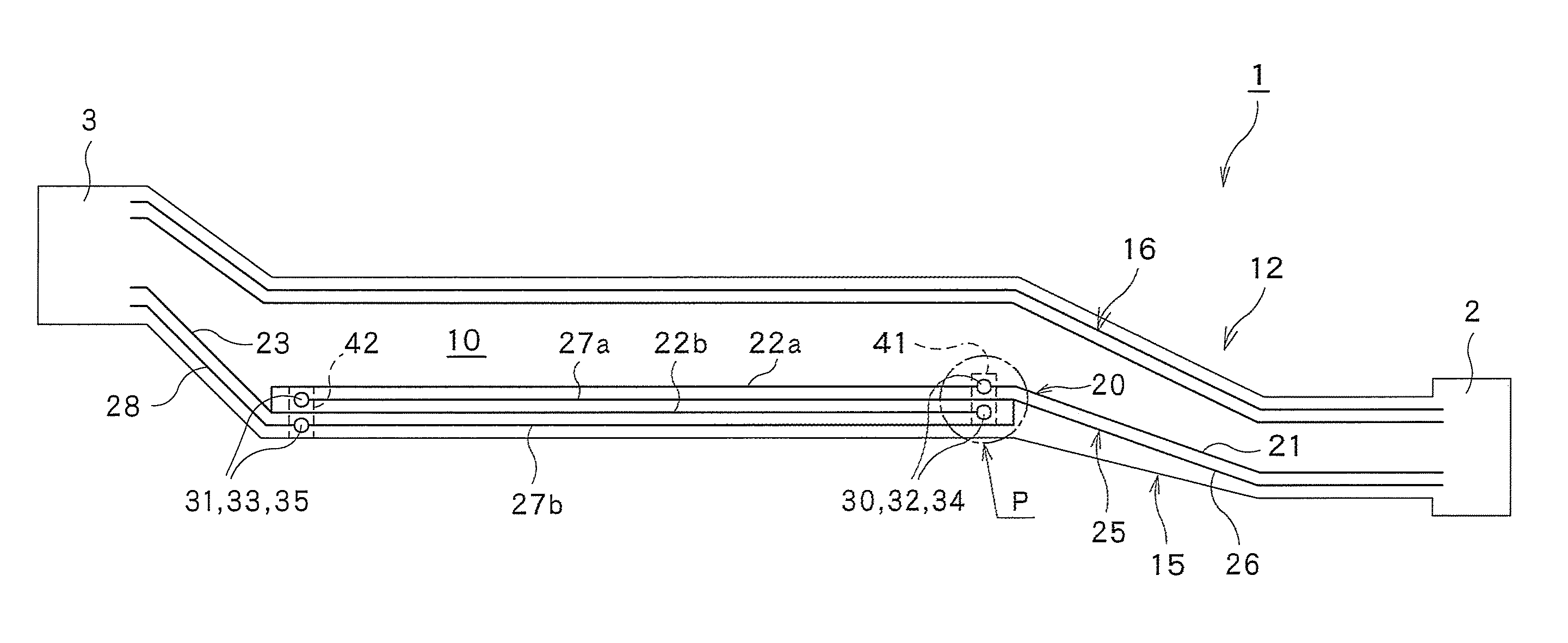
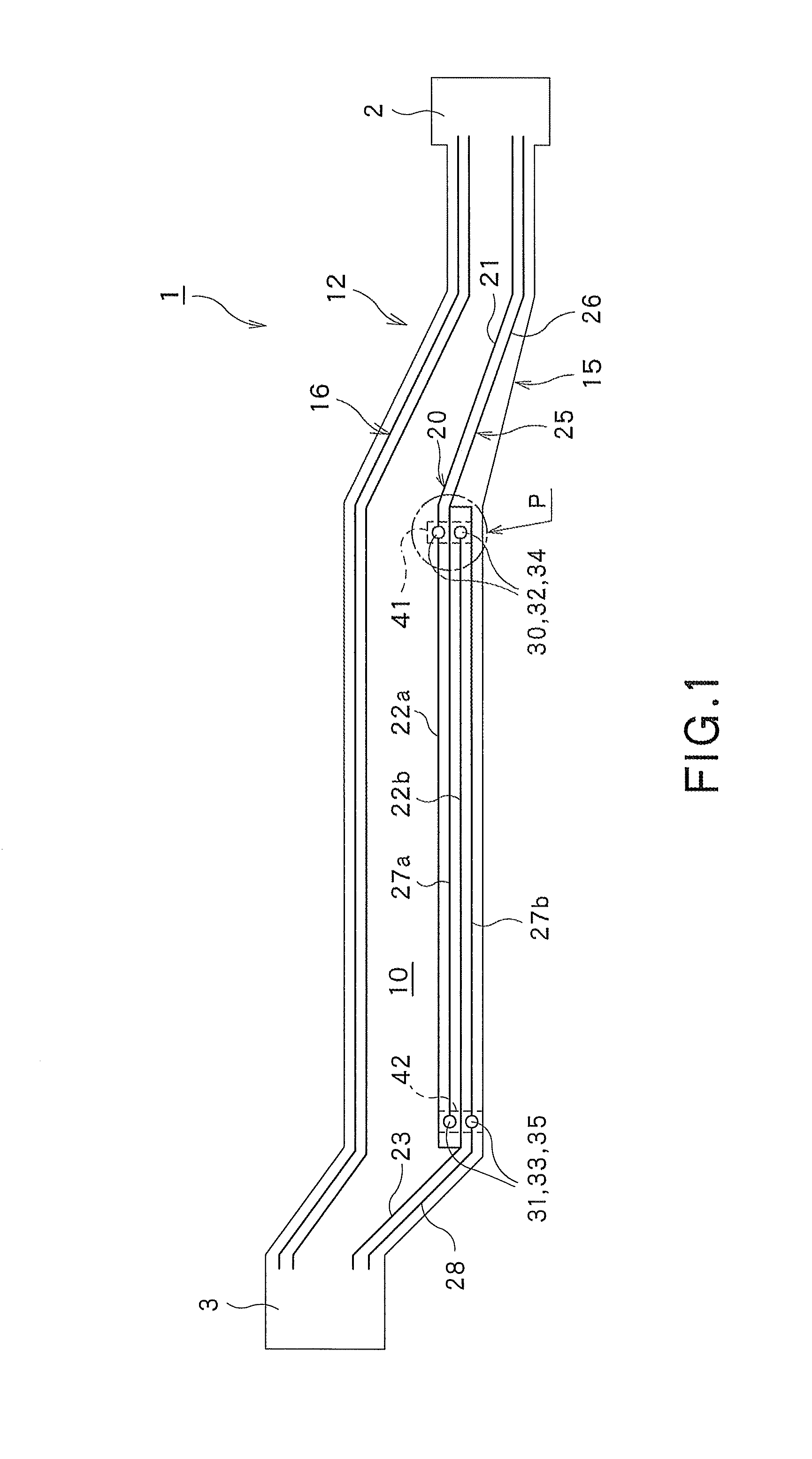
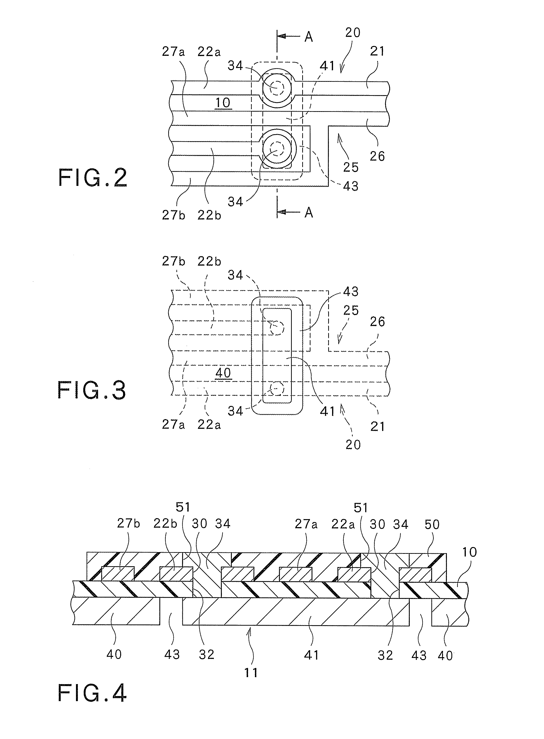
[0079]Now, referring to FIGS. 1 through 11, the suspension substrate, suspension, head suspension, hard disk drive and method for manufacturing the suspension substrate, respectively related to the first embodiment, will be described.
[0080]As shown in FIG. 1, the suspension substrate 1 is provided to extend from the head portion 2 on which the slider 72 that will be described later (see FIG. 6) is mounted, to the tail portion 3 to which the external connector substrate 73 is connected.
[0081]As shown in FIGS. 1 and 4, the suspension substrate 1 includes the insulating layer 10, the spring material layer (metal support substrate) 11 provided on one face of the insulating layer 10 and having the conductivity, and the plurality of (e.g., four) wirings 12 respectively provided on the other face of the insulating layer 10. Among the four wirings 12, two wirings 12 constitute the pair of writing wirings 15 (i.e., a first writing wiring 20 and a second writing wiring 25) arranged adjacent t...
second embodiment
[0115]Now, referring to FIG. 12, the method for manufacturing the suspension substrate related to the second embodiment, will be described.
[0116]Except for a key point that each wiring is formed by the so-called additive method, the second embodiment shown in FIG. 12 is substantially the same as the first embodiment shown in FIGS. 1 through 11. Therefore, in FIG. 12, each like part or portion of the first embodiment shown in FIGS. 1 through 11 is designated by each like reference numeral or character also shown therein, and the explanation of that part or portion will be omitted below.
[0117]In this embodiment, first of all, as shown in FIG. 12(a), the spring material layer 11 is prepared.
[0118]Then, the insulating layer 10 having the insulating through-holes 32, 33 is formed on the spring material layer 11 (see FIG. 12(b)). In this case, the insulating layer 10 consisting of the non-photosensitive material is first formed on the spring material layer 11, and then a pattern of a prop...
third embodiment
[0125]Next, referring to FIGS. 13 through 17, the suspension substrate related to the third embodiment of the present invention will be described.
[0126]In the third embodiment shown in FIGS. 13 through 17 one wiring, including the head-side wiring part and plurality of division wiring parts respectively bifurcated from the head-side wiring part constitutes a power source wiring for supplying the electric power to the slider. However, except for this key point, this embodiment is substantially the same as the first embodiment shown in FIGS. 1 through 11. Therefore, in FIGS. 13 through 17, each like part or portion of the first embodiment shown in FIGS. 1 through 11 is designated by each like reference numeral or character also shown therein, and the explanation on that part or portion will be omitted below.
[0127]As shown in FIGS. 13 and 14, the pair of writing wirings 15, pair of reading wirings 16 and power source wiring 90 for supplying the electric power to the slider 72 are respe...
PUM
| Property | Measurement | Unit |
|---|---|---|
| width | aaaaa | aaaaa |
| thickness | aaaaa | aaaaa |
| thickness | aaaaa | aaaaa |
Abstract
Description
Claims
Application Information
 - R&D
- Intellectual Property
- Life Sciences
- Materials
- Tech Scout
- Unparalleled Data Quality
- Higher Quality Content
- 60% Fewer Hallucinations
Browse by: Latest US Patents, China's latest patents, Technical Efficacy Thesaurus, Application Domain, Technology Topic, Popular Technical Reports.
© 2025 PatSnap. All rights reserved.Legal|Privacy policy|Modern Slavery Act Transparency Statement|Sitemap|About US| Contact US: help@patsnap.com


