Rotary cutter for mowing machine

一种旋转刀具、割草机的技术,应用在收割机、农业机械和机具、切割器等方向,能够解决重量增加、抽出绳索危险、结构复杂等问题,达到稳定抽出长度的效果

Active Publication Date: 2007-10-31
STARTING IND CO LTD
View PDF1 Cites 9 Cited by
  • Summary
  • Abstract
  • Description
  • Claims
  • Application Information

AI Technical Summary

Problems solved by technology

However, the method of extracting the rope by pressing the knife against the ground or striking the knife is dangerous due to the possibility of scattering small stones
In addition, the method of increasing the rotational speed will lead to a complex structure and increased weight, and the rotational speed must be increased to the highest level to extract the rope
Therefore, these methods all have such a problem that the motor and cutter as the power source are subjected to excessive strain, and at the same time, the rope cannot be drawn out stably, and it is dangerous for the rope to be drawn out.

Method used


Image

  • Rotary cutter for mowing machine
  • Rotary cutter for mowing machine
  • Rotary cutter for mowing machine

Examples


Embodiment Construction

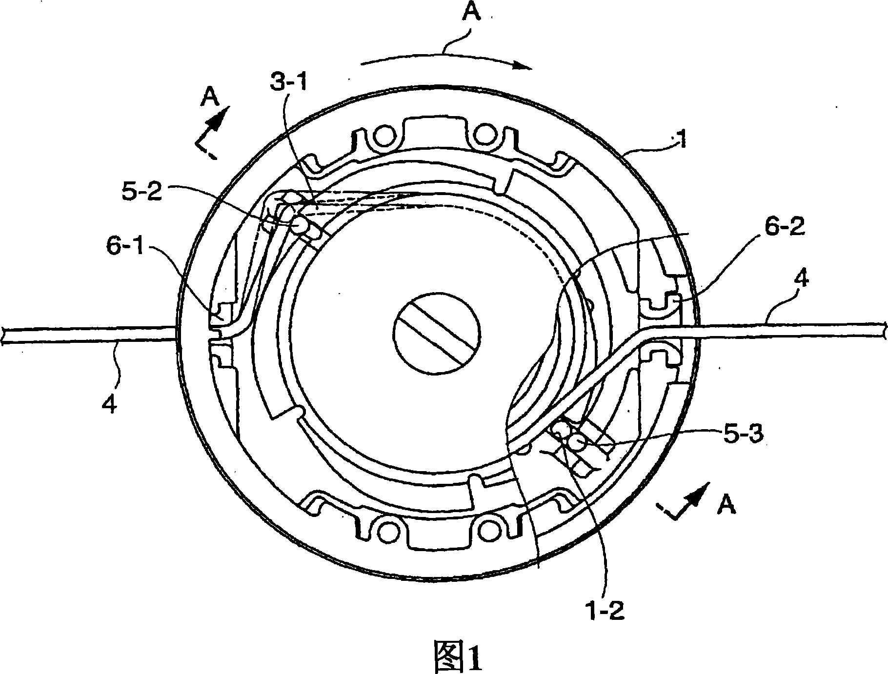
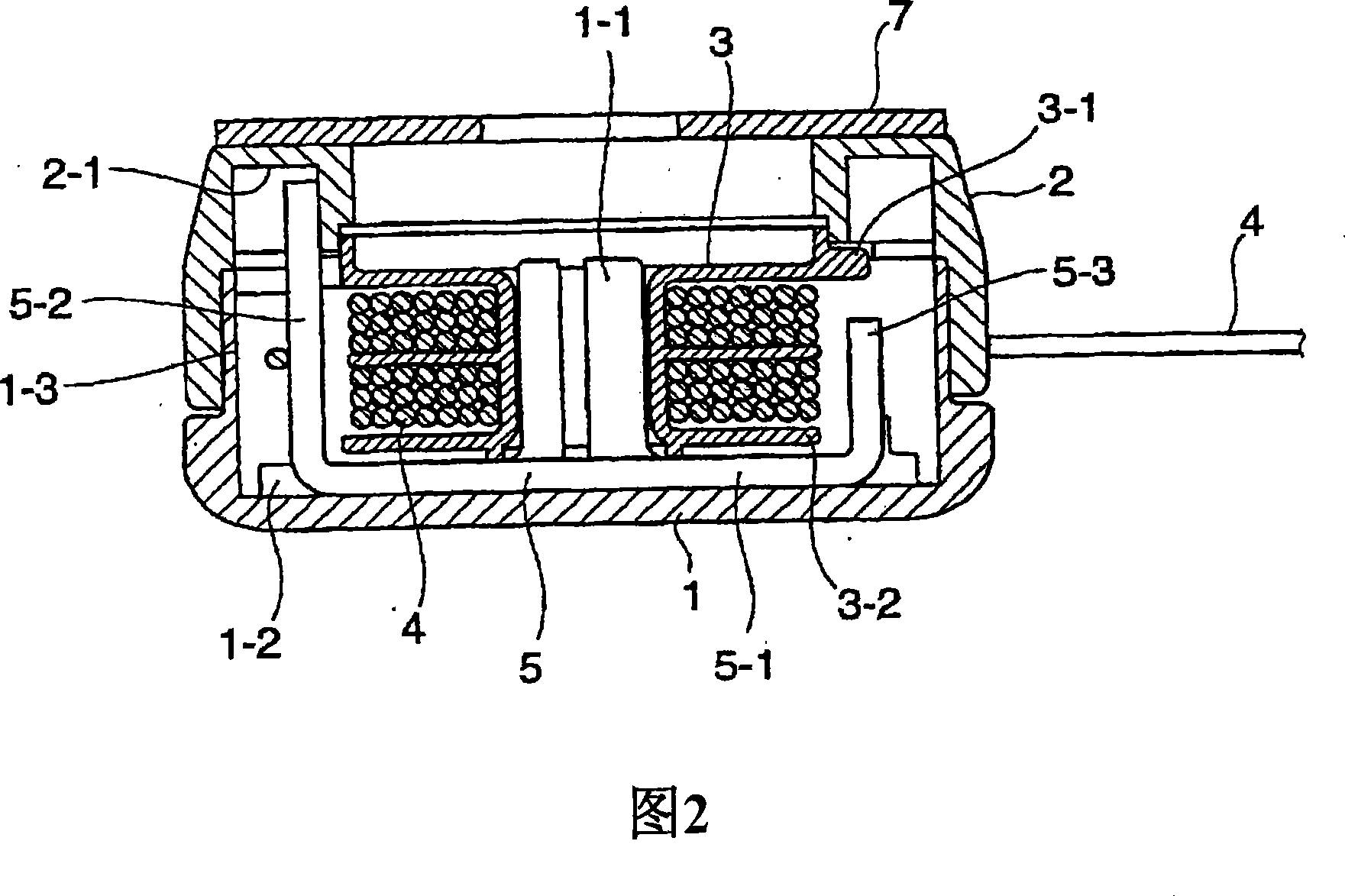
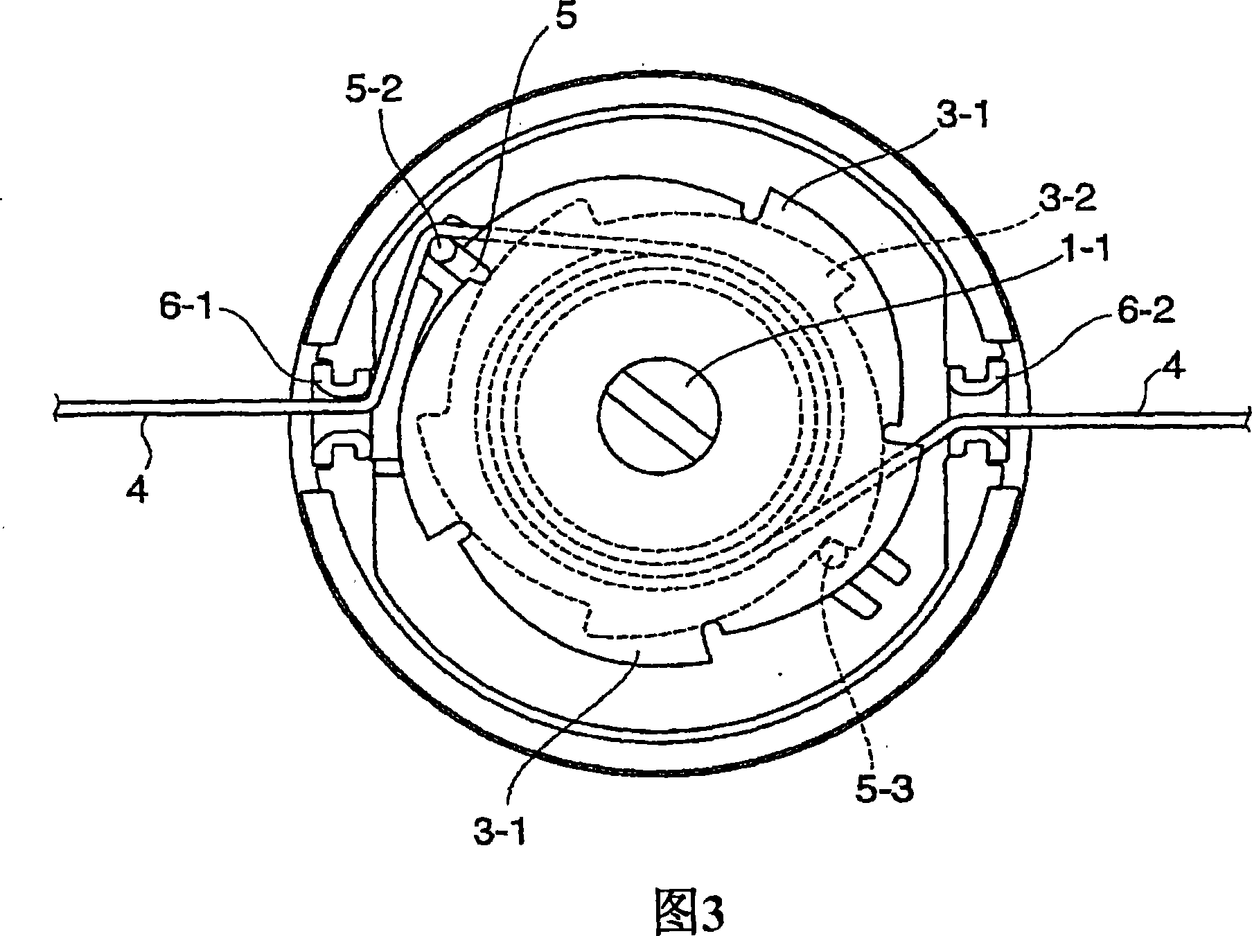
[0026] Fig. 1 is a partial sectional plan view of a rotary cutter according to a first embodiment of the present invention, Fig. 2 is a sectional view along line A-A in Fig. 1, Fig. 3 is a rotary cutter in Fig. 1, the stopper is in contact with the reel A plan view of the state where the upper cams are engaged, FIG. 4 is a plan view of a state where the stopper is guided by the lower cam of the reel in the rotary cutter of FIG. 1 , and FIG. 5 is a partially cutaway plan view of a second embodiment of the present invention, Fig. 6 is a sectional view along the B-B line in Fig. 5, Fig. 7 is a partial sectional plan view of the third embodiment of the present invention, Fig. 8 is a partial sectional plan view of the fourth embodiment of the present invention, Fig. 9 is a fifth embodiment of the present invention Partial sectional plan view of the embodiment, FIG. 10 is a partial sectional plan view of the sixth embodiment of the present invention, FIG. 11 is a view corresponding t...


PUM


Abstract

A rotary cutter for a mowing machine includes a cord for mowing grass by rotating, a reel which contains the cord and intermittently rotates to pay out the cord, a case which contains the reel, and a cover which covers the case, wherein the reel includes an upper cam and a lower cam, a stopper is incorporated in the case at a center of a bottom thereof, one end of the stopper is engaged with the upper cam thereby to stop the rotation of the reel, the other end of the stopper is engaged with the lower cam, one end of the cord is engaged with the stopper from outside thereof and guided out of the rotary cutter through a cord guide, and the other end of the cord is guided out of the rotary cutter without touching the stopper.

Description

technical field [0001] The present invention relates to lawnmower rotary cutters for mowing grass or the like by means of a cord (usually made of nylon), wherein the cord is drawn out in a radial direction of a housing which is rotated by the drive power of a motor or the like Shaft drive, and more specifically, the present invention relates to rotary knives where the cord is automatically withdrawn when the cord has worn and shortened. Background technique [0002] Typically, the prevailing method for such rotary knives is that a nylon cord is housed in a reel, and in order to extract the cord as it wears out, the cord can be withdrawn during rotation by pressing the knife against the ground, tapping the knife, or increasing the rotational speed of the knife. However, the method of extracting the rope by pressing the knife against the ground or striking the knife is dangerous due to the possibility of scattering small stones. In addition, the method of increasing the rotat...

Claims


Application Information

Patent Timeline
Patent Type & Authority Applications(China)
IPC IPC(8): A01D34/416
CPCA01D34/4162
Inventor 柴崎稔加藤宏树
Owner STARTING IND CO LTD
Why Eureka
Try Eureka