Conducting wire protection mechanism

A wire protection and wire technology, which is applied in nonlinear optics, instruments, optics, etc., can solve the problems of wire cut lighting, light source wire cut, no light, etc.

Inactive Publication Date: 2007-10-31
CHUNGHWA PICTURE TUBES LTD
View PDF0 Cites 4 Cited by
  • Summary
  • Abstract
  • Description
  • Claims
  • Application Information

AI Technical Summary

Problems solved by technology

This will cause the bad situation that the light source wire is cut by the metal edge of the back plate, and in severe cases, it will cause the wire to be cut and cause the problem of not turning on the light

Method used


Image

  • Conducting wire protection mechanism
  • Conducting wire protection mechanism
  • Conducting wire protection mechanism

Examples


Embodiment Construction

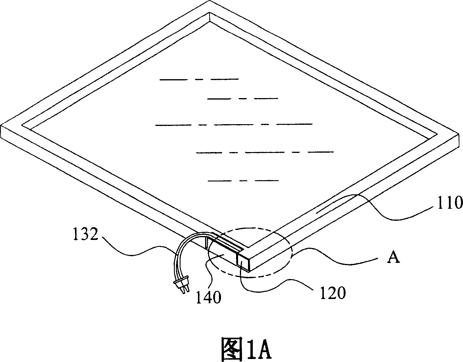
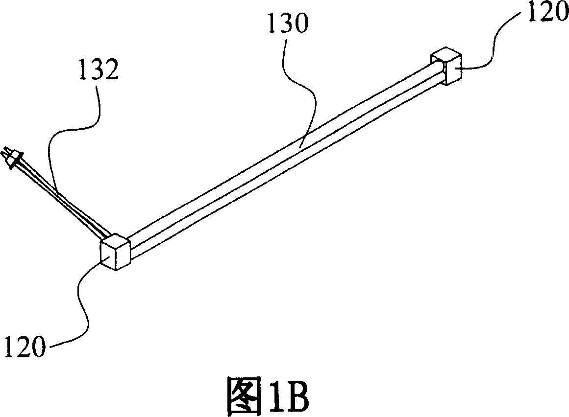
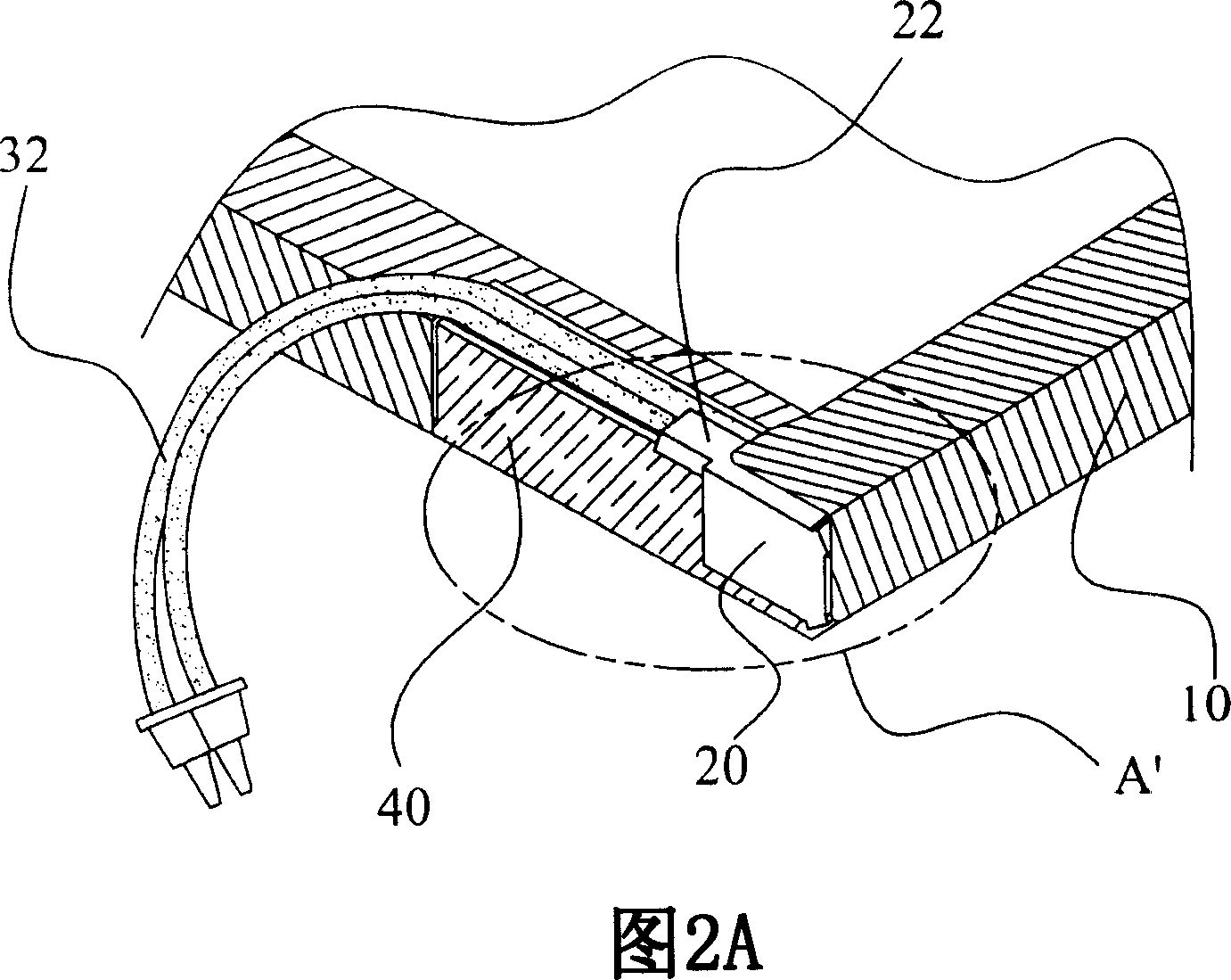
[0027] FIG. 2A and FIG. 2B are detailed schematic diagrams of outlet terminals of a backlight module according to an embodiment of the present invention. In this embodiment, the wire protection mechanism at the wire outlet A' of the backlight module includes a back plate 10 , a holding element 20 , a light source wire 32 and a buffer pad 22 . In the backlight module, the back plate 10 is used to arrange a light source 30 thereon, such as a cold cathode tube or a hot cathode tube, and the holding element 20 is used to fix and receive the light source 30 . The backplane 10 has an outlet A' located on one side of the backplane 10. The light source wire 32 is led out from the outlet end A' through the holding element 20. Wherein, a buffer pad 22 is disposed at the wire outlet A to separate the light source wire 32 from the edge of the back panel 10 .

[0028] Continuing the above description, in this embodiment, the material of the back plate 10 is metal, such as aluminum plate....


PUM


Abstract

This invention relates to one line protection structure, which comprises the following parts: one back board to set at least one light source on back board with one exit end on one side of back board; one fix element to fix lamp source; one light source wire to fix element exit through exit end; one buffer pad set in exit end to isolate lamp source wire and back board; the wire protection structure aphototropism module by use of one buffer pad to isolate lamp source wire and back board to avoid lamp source wire cut for dead light.

Description

technical field [0001] The invention relates to a backlight module, in particular to a wire protection mechanism for the outlet end of the backlight module. Background technique [0002] In recent years, liquid crystal display has been widely used. With the improvement of driving technology, it has the advantages of low power consumption, thin and light weight, and low driving voltage. It has been widely used in mobile communication equipment, video recorders, Laptops, desktop monitors, and various projection devices. Generally, a more common liquid crystal display is a thin film transistor display. Since the thin film transistor display itself does not emit light, it needs to use a light source of a backlight module to achieve an image display effect. No matter what type of light source is used, during the assembly process of the backlight module, the lead wire of the light source needs to be led out from the outlet end of the backlight module for voltage application. [...

Claims


Application Information

Patent Timeline
Patent Type & Authority Applications(China)
IPC IPC(8): G02F1/13357G02F1/1333G02F1/1335
Inventor 徐伟真王耀东
Owner CHUNGHWA PICTURE TUBES LTD
Why Eureka
Try Eureka