
Controlling task execution

A technology for controlling tasks and tasks, applied in the direction of program control design, multi-programming devices, instruments, etc., to achieve the effect of reducing a large number of links

Active Publication Date: 2010-07-07
INITIO TECH
View PDF5 Cites 0 Cited by
  • Summary
  • Abstract
  • Description
  • Claims
  • Application Information

AI Technical Summary

Problems solved by technology

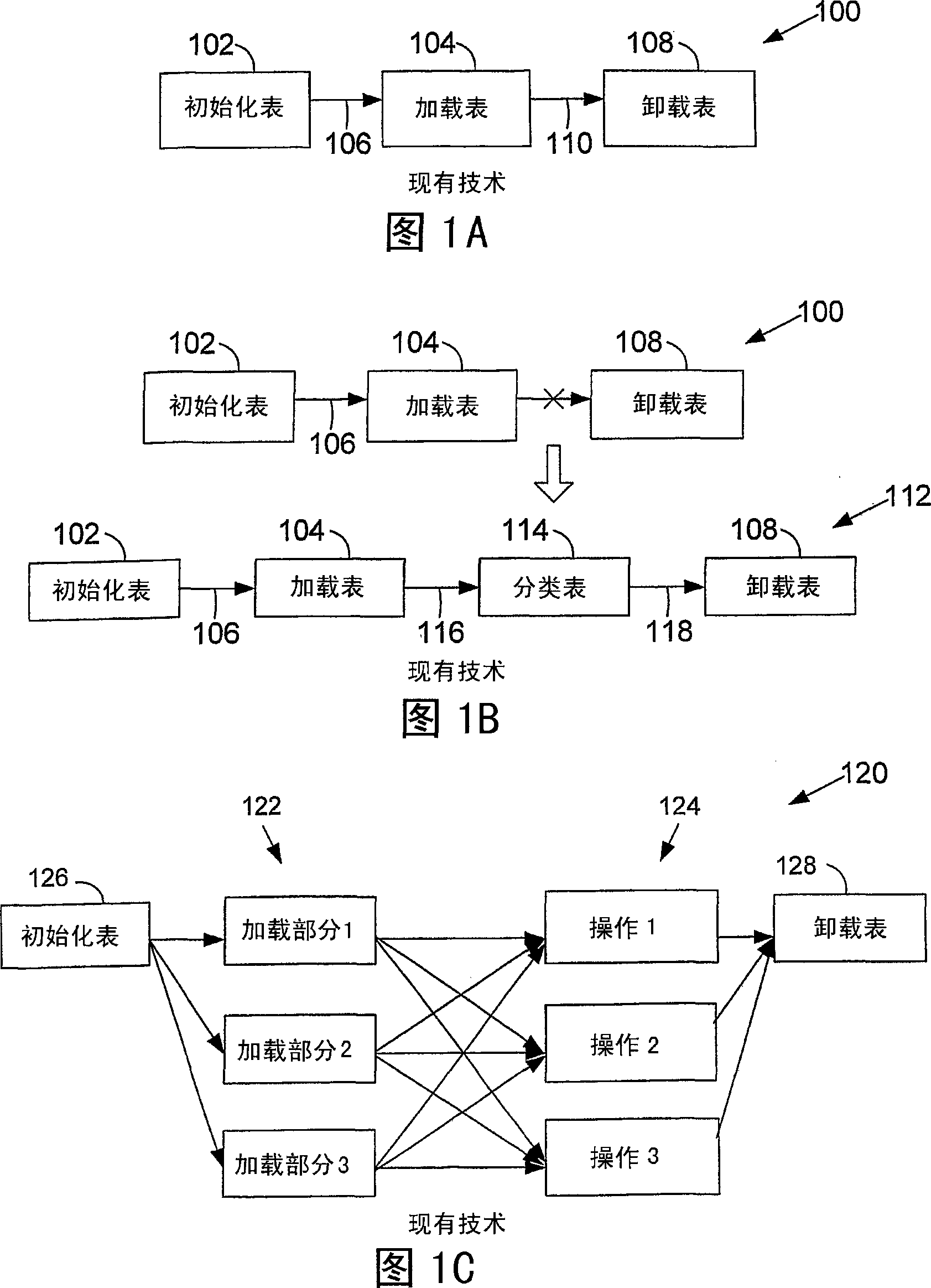
This example shows the potential complexity that can exist in some dependency graphs

Method used


Image

  • Controlling task execution
  • Controlling task execution
  • Controlling task execution

Examples


Embodiment Construction

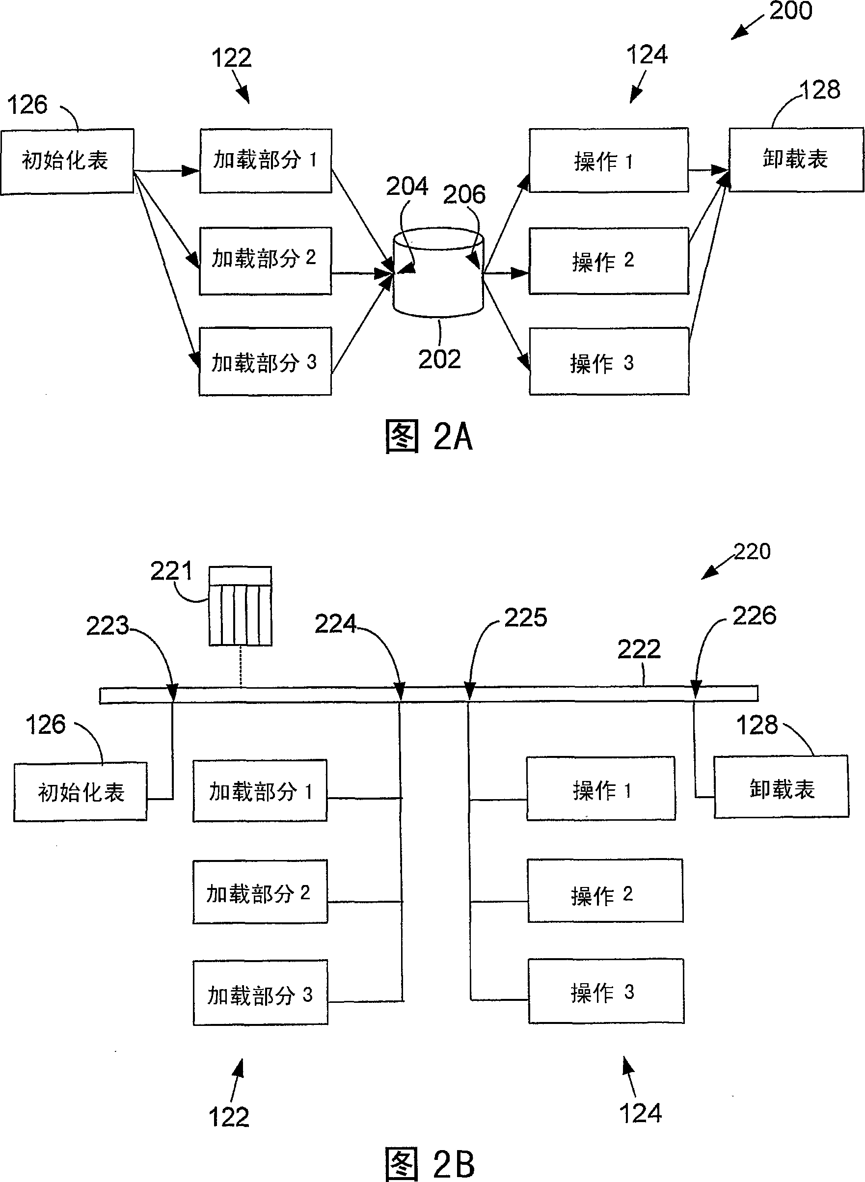
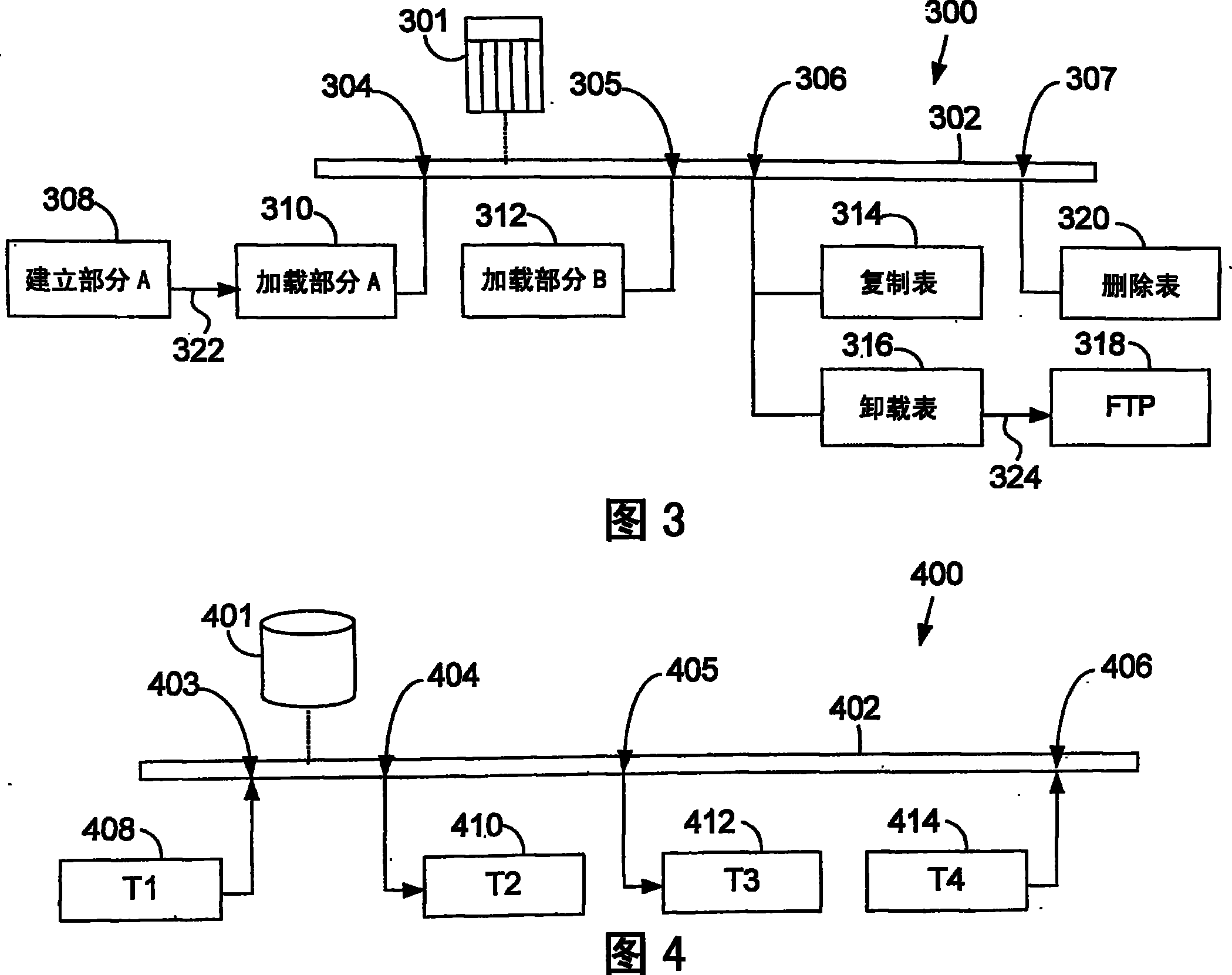
[0025] One method for satisfying dependency constraints between executing or initializing tasks in a runtime environment is by performing a control process that accepts a graphical representation of dependencies as a specification of those dependencies. The control process initiates the execution of tasks (in the same or different execution environments) based on the graphical representation of task dependencies. For example, the user can use the graphical user interface to associate the nodes and links of the graph with tasks and dependencies, respectively, thereby creating a dependency graph. Alternatively, a dependency graph may be automatically generated based on explicit or implied ordering constraints. Once the dependency graph is generated, the user can view the dependency graph through a graphical user interface.

[0026] A first way to express constraints in the dependency graph associated with groups of tasks (which interact with resources) is to include resource un...


PUM


Abstract

A specification of a graphical representation of task dependency has a plurality of task elements each associated with a different task, a resource element having a plurality of attachment locations, and linking elements coupling the task elements to the resource element at the plurality of associated attachment locations. Associations of task elements to attachment locations on the resource element specify an ordering constraint on the tasks associated with the task elements. The tasks are executed according to the graphical representation of task dependency.

Description

technical field [0001] The present invention relates to the execution of control tasks. Background technique [0002] Computational tasks in a computing system often have dependencies that lead to the constraint that some tasks need to start or complete execution before or after other tasks are performed. Partial sequencing of tasks can be used to satisfy this constraint. Tasks are performed by processes running in the same or a different execution environment than some of the tasks that may be running concurrently. Control processing may be performed to initiate and monitor the execution of tasks according to the description of task dependency constraints. [0003] Figure 1A shows an example of a graph representing dependencies between tasks, a "dependency graph". Nodes represent tasks, and directed links represent dependency constraints. In this instance, the dependencies between tasks arise from access to a common data structure (in this case a table). The initialize...

Claims


Application Information

Patent Timeline
Patent Type & Authority Patents(China)
IPC IPC(8): G06F9/46G06F9/48
CPCG06F9/4881G06F2209/484G06F9/522
Inventor 弗兰克·因金戈洛克雷格·W.·斯坦菲尔
Owner INITIO TECH
Learn More