Driving mechanism for mobile door lock

A driving mechanism and door lock technology, applied in the field of sliding door locks, can solve the problems of heavy and stiff hand feeling, complex structure, easy wear, etc., and achieve the effects of reducing mechanical friction, good hand feeling, and simple lock body structure

Inactive Publication Date: 2007-11-28
GUANGDONG ARCHIE HARDWARE
View PDF0 Cites 6 Cited by
  • Summary
  • Abstract
  • Description
  • Claims
  • Application Information

AI Technical Summary

Problems solved by technology

Wherein, the positioning plate guide shaft 60 mainly realizes the guidance to the limit arm 20, so that the limit arm 20 slides along the track defined by the positioning plate guide shaft 60, and the main functions of the limit arm 20 and the return spring 21 are It is to position the toggle wheel 3 so as to realize the positioning of the position of the positioning plate 7 and the dead bolt 8 driven by the toggle wheel 3, because the protrusion 30 of the toggle wheel 3 directly pushes the arc end 201 of the limit arm 20 , belongs to the rigid mechanical connection, the mechanical friction between the two, the resistance of the knob or the lock cylinder is large when rotating, so it is not only easy to wear, but also feels heavy and stiff and has a complicated structure

Method used


Image

  • Driving mechanism for mobile door lock
  • Driving mechanism for mobile door lock
  • Driving mechanism for mobile door lock

Examples


Embodiment 1

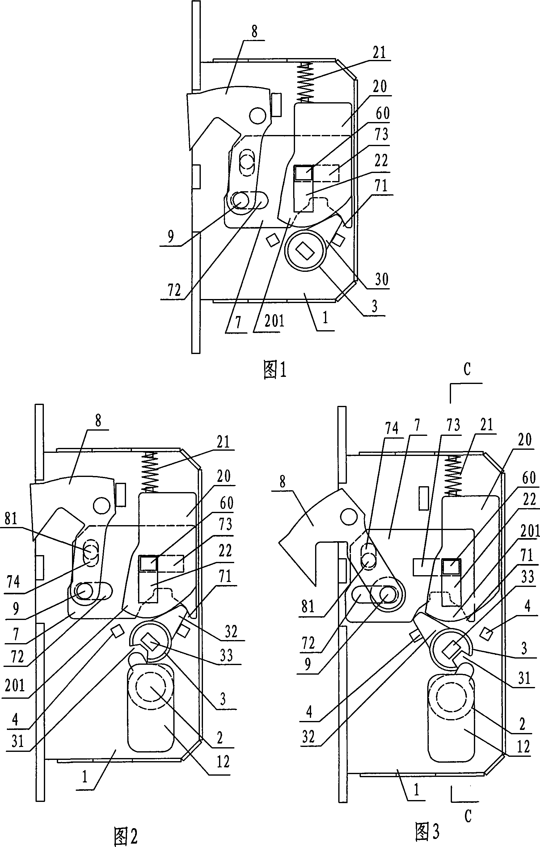
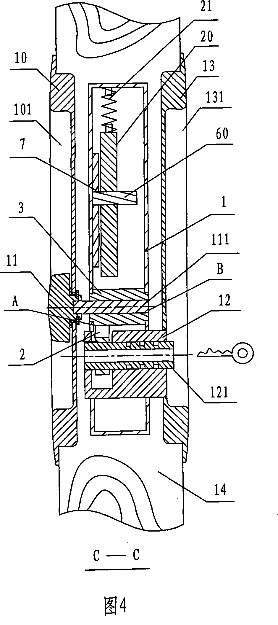
[0033] As shown in Figures 2, 3, and 4, a driving mechanism for a sliding door lock includes a lock case 1, a toggle wheel 3 accommodated in the lock case 1; and a lock cylinder 12 fixed in the lock body, The axial tail end of the lock cylinder 12 is provided with a shift fork 2 that can rotate coaxially with the lock cylinder 121, and a shift fork opening 31 is also provided on the side of the toggle wheel 3; The misalignment of the central axis of the wheel 3 is parallel to the central axis of the inner knob 11 and separated by a certain distance. On the side of the toggle wheel 3 and at a symmetrical position of 180 degrees with the toggle arm 32, a shift fork opening 31 is provided, and the shift fork 2 of the lock cylinder 12 stretches into the shift fork opening 31 to form a transmission connection. The shape and size of the shift fork opening 31 on the toggle wheel 3 and the shift fork 2 are compatible with each other. When the lock cylinder 12 is turned, the transmissi...

Embodiment 2

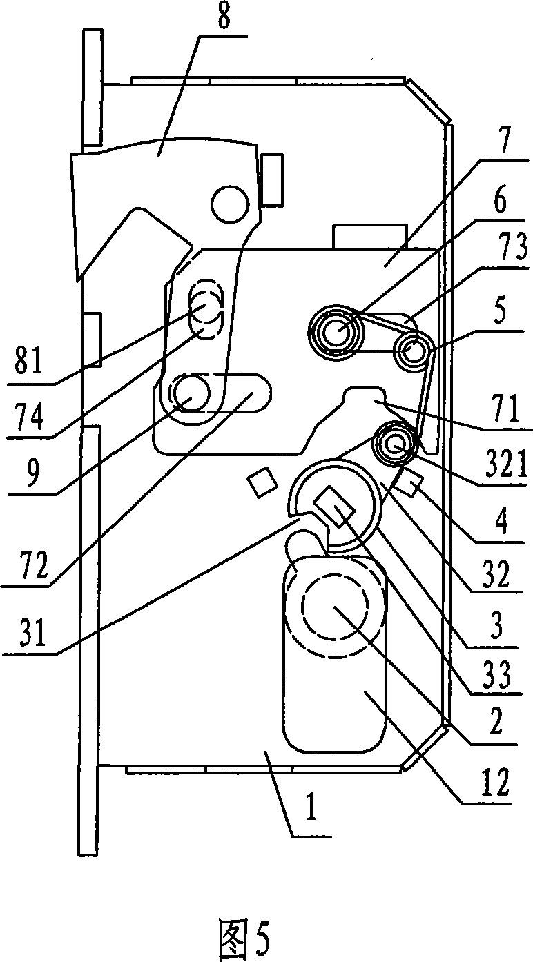
[0044] As shown in Figures 5, 6, and 7, the difference from Embodiment 1 is that the driving mechanism of the sliding door lock includes three coils of special-shaped springs 5, the spring positioning shaft 6 fixed on the lock housing 1, and the three coils of special-shaped springs 5 ​​are fixed. It is connected between the toggle arm 32 and the spring positioning shaft 6, thereby replacing the positioning plate guide shaft 60, the limit arm 20 and the limit arm return spring 21 in the prior art with three rings of special-shaped springs 5. The position-limiting mechanism of toggle wheel 3 and positioning plate 7.

[0045] The spring positioning shaft 6 is located in the area where the positioning plate 7 is located, and can also be arranged outside the area where the positioning plate 7 is located. For the sake of simplicity in structure, it is preferable to arrange the spring positioning shaft 6 in the area where the positioning plate 7 is located, and use the spring positi...


PUM


Abstract

The invention discloses a driving mechanism of shift door lock, comprising lock shell, dialing wheel accommodated in the lock shell and lock core fixed in the lock body. At the axial tail end of lock core shifting fork, which can rotate in coaxial axis, can be set and shifting fork port is also set at the side of said dialing wheel. The central axial line of said lock core is dislocation with the central axial line of said dialing wheel. The shifting fork of said lock core extends into said shifting fork port. Other mechanisms matched with the driving mechanism of shifting door lock also comprises lock tongue accommodated in the lock shell, locating shaft of lock tongue, locating plate and guiding shaft of locating plate. When lock is opened and closed, the key inserts into the lock core to rotate shifting fork and the shifting fork inserts into the shifting fork port set on the dialing wheel to drive the dialing wheel rotate in the opposite direction. The dialing wheel drives the locating plate slide along the guiding shaft of locating plate. The locating plate drives the lock tongue bounce in or out of lock shell on the locating shaft of lock tongue. The invention makes the shift door lock high safety. It can be applied in shift door lock needed in various shift doors.

Description

technical field [0001] The invention relates to a sliding door lock, in particular to a driving mechanism of a sliding door lock. Background technique [0002] As shown in Figure 1, the existing sliding door lock includes a lock housing 1, a lock tongue 8 in the shape of a jun, a positioning plate 7, a toggle wheel 3, a limit arm 20, a limit arm return spring 21 and a lock fixed on the lock housing. The positioning plate guide shaft 60 and the dead bolt positioning shaft 9 in 1, the dead bolt 8, the positioning plate 7, the limit arm 20, the limit arm return spring 21 and the toggle wheel 3 are accommodated in the lock housing 1; It is rotatably fixed on the deadbolt positioning shaft 9, and a boss is set in the middle and inserted into the hole provided in the positioning plate 7 to form a rocker mechanism; one side of the positioning plate 7 is provided with a transmission fork 71, and two long forks are arranged in the middle. Strip-shaped sliding notches 72, 73, the pos...

Claims


Application Information

Patent Timeline
Patent Type & Authority Applications(China)
IPC IPC(8): E05B65/08
Inventor 曹湛斌邱家求
Owner GUANGDONG ARCHIE HARDWARE
Why Eureka
Try Eureka