Flushing and seat sterilization device on toilet

A technology for flushing toilets and post-cleaning, which can be used in disinfection, toilet seats or covers, sanitary equipment for toilets, etc.

Inactive Publication Date: 2007-12-19
潘定国
View PDF8 Cites 21 Cited by
  • Summary
  • Abstract
  • Description
  • Claims
  • Application Information

AI Technical Summary

Problems solved by technology

In the existing device, the drainage mechanism is inserted into the water tank of the water flushing mechanism from above, and then connected to the fl

Method used


Image

  • Flushing and seat sterilization device on toilet
  • Flushing and seat sterilization device on toilet
  • Flushing and seat sterilization device on toilet

Examples


Embodiment Construction

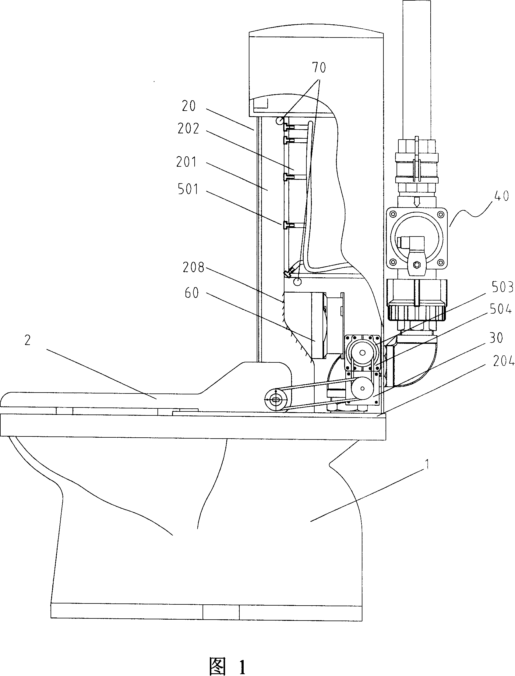
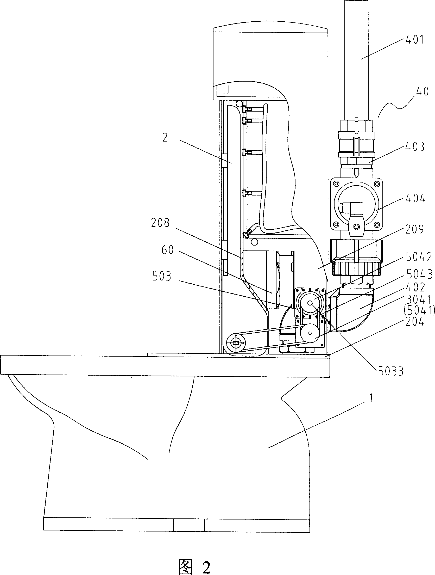
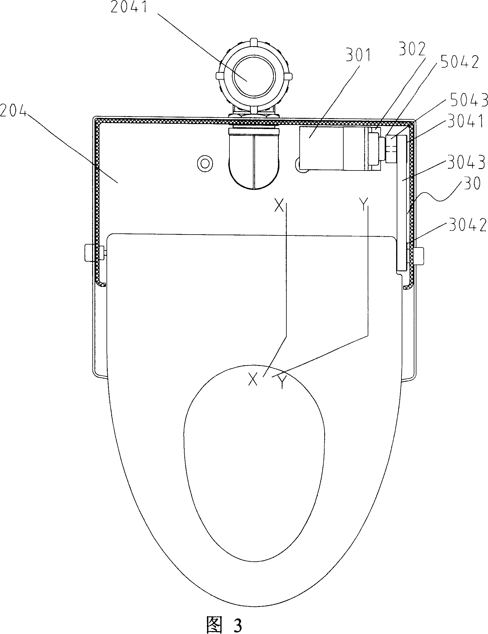
[0052] Please refer to Fig. 1 to Fig. 6, according to the flush toilet that is used for cleaning after defecation and seat ring disinfection according to the present invention, comprises toilet 1, seat ring 2, cleaning device and seat ring disinfection device after defecation, wherein, the cleaning device after defecating Including water inlet valve 3, decompression water tank 14, pump 4, water tank 5, rotary valve 6, injection devices 7 and 8 for flushing anus and yin, fan-shaped flushing pipe 9, valve control device 10, hot air unit 11, remote control 12 And the system control circuit 13.

[0053] Closet 1 basically adopts the closet of conventional internal structure, preferably selects the slightly larger width of its rear portion in appearance. The seat ring 2 is a combination of an upper ring and a lower bottom, and the rear part or the rear part of the upper ring is provided with a cover-like protrusion 21 that protrudes laterally to form a cavity 22 that is higher than...


PUM


Abstract

The present invention relates to a flush toilet capable of cleaning and disinfecting seat after use. It includes the following several portions: toilet bowl, seat, cleaning device after use, seat disinfecting device and control circuit. Said invention also provides the concrete structure and composition of above-mentioned every portion. Besides, said invention also provides the working principle of said flush toilet and its concrete operation method.

Description

technical field [0001] The invention relates to a flush toilet, in particular to a flush toilet for cleaning after defecating and disinfecting seat rings. Background technique [0002] Along with the development of society and the continuous improvement of people's living standards, the toilet cleaning device and the toilet seat cleaning and disinfection device as body cleaners are increasingly accepted and liked by the general public. They are popular because they provide people with a healthy, hygienic and disease-preventing lifestyle. [0003] The cleaning device after defecating can enable people to wipe their bodies without paper after defecating. The device in the prior art includes a rotary valve, a pump, a water tank, a valve control device and a nozzle device composed of a valve core, a valve body and a front and rear valve cover, wherein the cleaning function of the nozzle device is to flush the anus or flush the yin through the rotary valve. The spray body provi...

Claims


Application Information

Patent Timeline
IPC IPC(8): E03D9/00E03D9/08A47K13/00A61L2/00
CPCE03D9/08A47K13/302
Inventor 潘定国
Owner 潘定国
Why Eureka
Try Eureka