Retreating method for knitting yarn and flat knitting machine

A technology for knitting yarn and flat knitting machine, which is applied in the direction of flat knitting machine, knitting, weft knitting, etc.

Active Publication Date: 2012-05-30
SHIMA SEIKI MFG LTD
View PDF3 Cites 0 Cited by
  • Summary
  • Abstract
  • Description
  • Claims
  • Application Information

AI Technical Summary

Problems solved by technology

However, adding a device for controlling the supply amount of the knitting yarn and preventing tension fluctuation complicates the structure of the knitting machine and increases the manufacturing cost.

Method used


Image

  • Retreating method for knitting yarn and flat knitting machine
  • Retreating method for knitting yarn and flat knitting machine
  • Retreating method for knitting yarn and flat knitting machine

Examples


Embodiment Construction

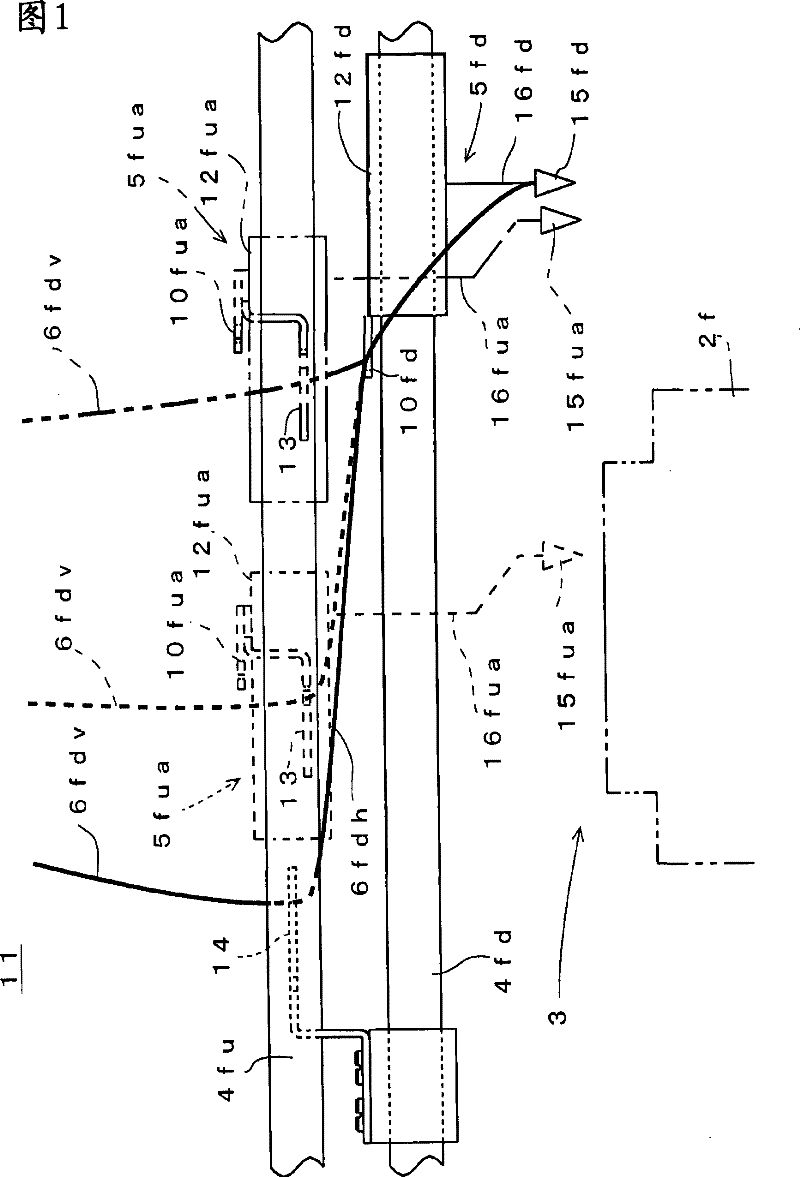
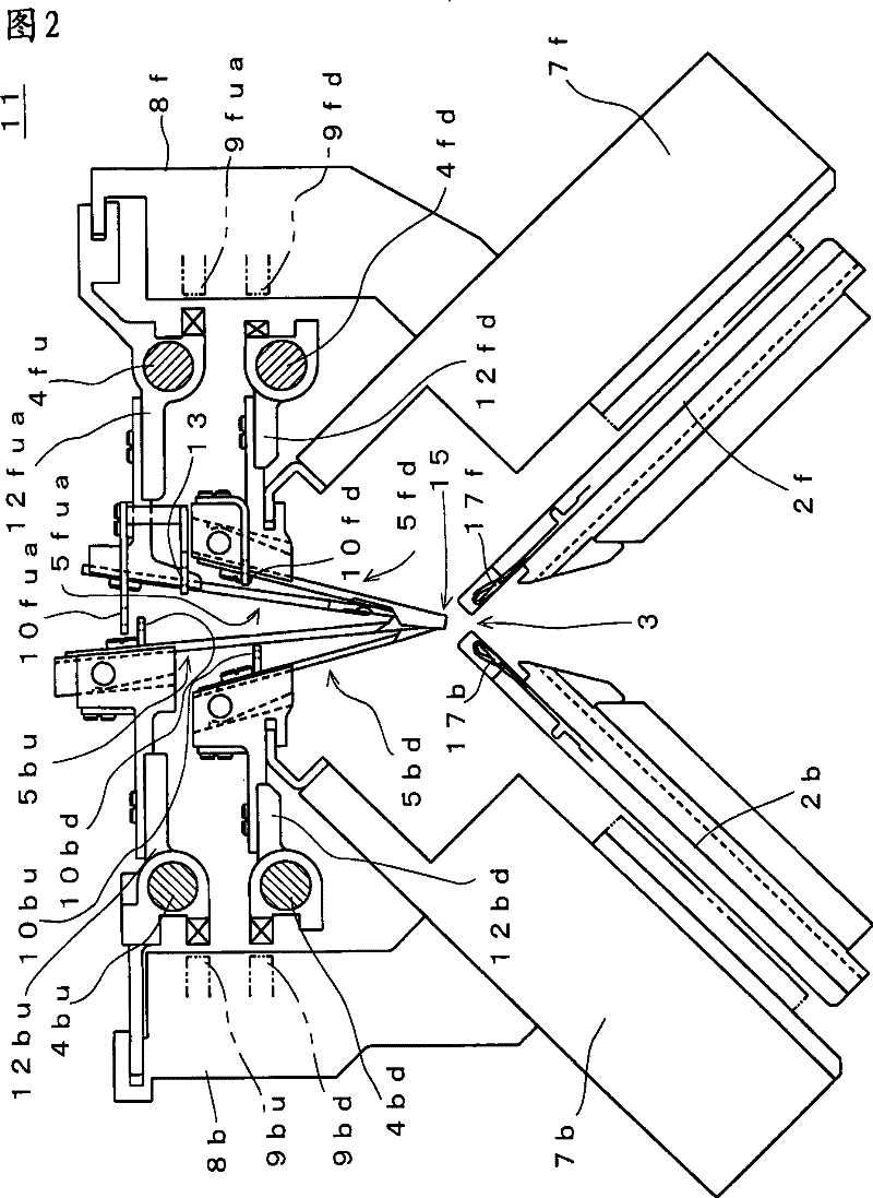
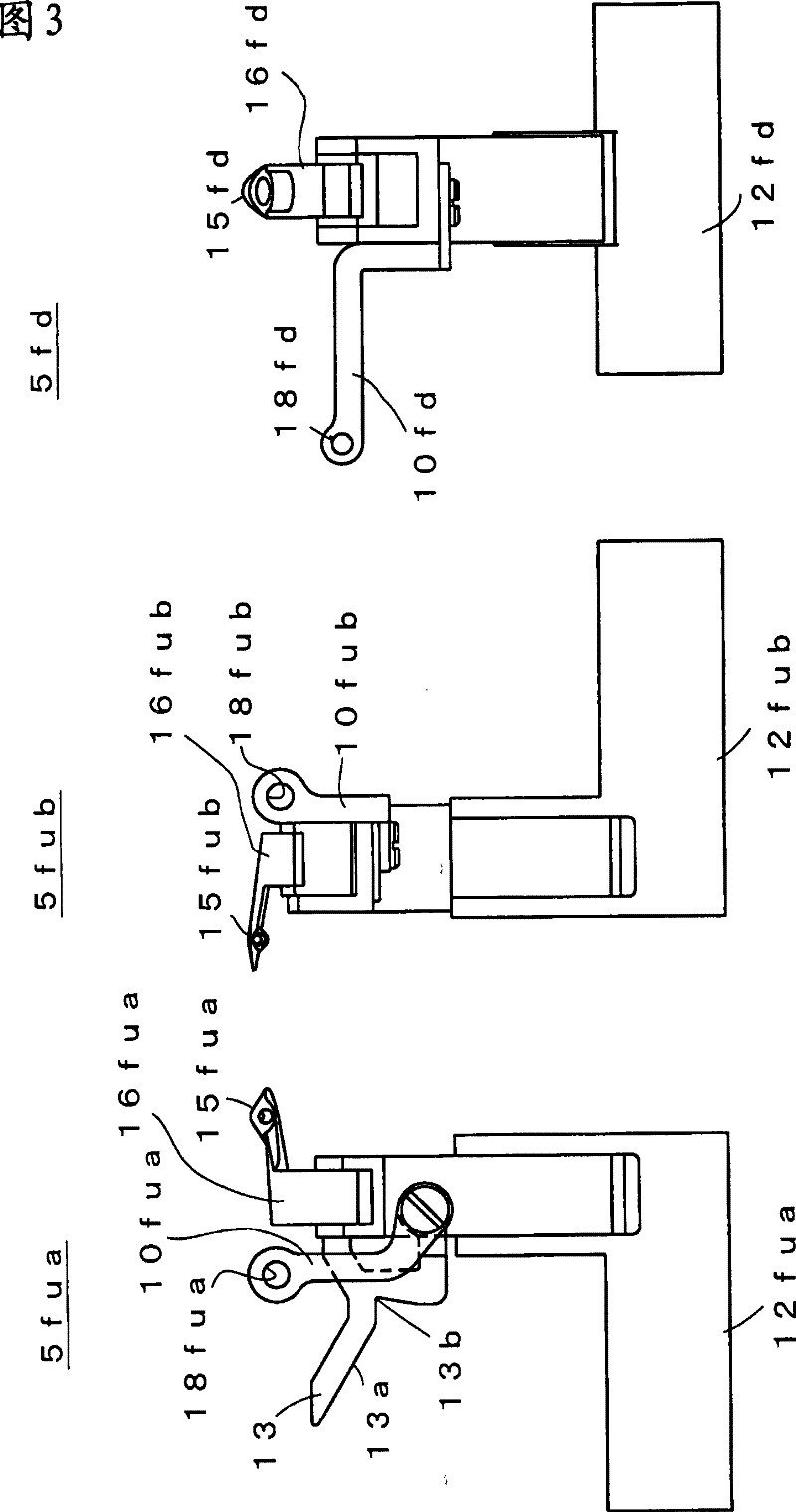
[0062] Figure 1 to Figure 6 The schematic structure of the sock knitting machine 11 which is one embodiment of this invention is shown. Also, in the description below, for the Figure 7 as well as Figure 8 The parts corresponding to the descriptions of the above and below are marked with the same symbols, and repeated descriptions are omitted. In addition, the description about the structure of the yarn feeders 5fua and 5fd described below also corresponds to other yarn feeders, and the description thereof will be omitted.

[0063] figure 1 and Figure 8 Correspondingly, the method of retracting the knitting yarn 6 in the sock knitting machine 11 of the present embodiment is shown. The configuration of each part is basically the same as Figure 7 same. Escape is performed to prevent interference when the yarn feeder 5fd provided on the lower traveling rail 4fd is stopped and the yarn feeder 5fua provided on the upper traveling rail 4fu is moved. Each of the yarn feede...


PUM


Abstract

The technical problem to be settled by the present invention is that it provides a retreating method for avoiding the interference between a stocking yarn which is permeable from top to bottom and a movable part and the horizontal loom. In the invention the carrying piece (13) of the upper thread feeder (5fua) knits the knitted fabric on one hand and it guides the top and bottom part (6fdv) of the stocking yarn to left side as the two-dot chain line showed on the other hand when the lower thread feeder (5fua) stops. Even if the top and bottom part (6fdv) is in the position where the interference is produced because of the moving of the top thread feeder (5fua), block it to the hook component (14) as the solid line shows the horizontal part (6fdh) between the hook component (14) and the feed carrier (10fd) will not interfere with the thread feeder (5fua). As the thread feeder (5fua) do knitting to the knitted fabric on one hand and on the other hand it moves the carrying piece (13) andthread feeder (5fd) to the position of the hook component (14) when it switches from the stop to the using, thereby it can release the blocking of the stocking yarn so it can be used in the state that the yarn is feed at the upper part.

Description

technical field [0001] The present invention relates to a knitting yarn retracting method and a flatbed knitting machine when knitting a knitted fabric while feeding a knitting yarn from above. Background technique [0002] Conventionally, in a flatbed knitting machine, knitting yarn is supplied while driving knitting needles arranged in parallel on the needle bed by a cam mechanism mounted on a carriage that reciprocates in the longitudinal direction of the needle bed, thereby knitting a knitted fabric. The knitting yarn is supplied from the yarn supply opening at the front end of the yarn feeder that moves with the carriage to the knitting needles that enter and leave the needle bed. As a method of supplying the knitting yarn to the yarn feeder, the yarn is fed from above through a buffer mechanism called a top spring installed on the upper part of the flat knitting machine, or the yarn is passed from the top spring through the side of the flat knitting machine. The yarn ...

Claims


Application Information

Patent Timeline
Patent Type & Authority Patents(China)
IPC IPC(8): D04B15/38D04B15/36D04B7/00
CPCD04B1/126D04B1/26D04B7/26D04B7/30D04B15/48D04B15/56D04B15/60D04B15/96D04B35/02
Inventor 下村博则
Owner SHIMA SEIKI MFG LTD
Why Eureka
Try Eureka