Electronic equipment having battery cover

A technology for electronic equipment and battery covers, which is applied to battery pack components, circuits, electrical components, etc., and can solve problems such as difficulty in opening the cover

Active Publication Date: 2008-01-02
CASIO COMPUTER CO LTD
View PDF1 Cites 11 Cited by
  • Summary
  • Abstract
  • Description
  • Claims
  • Application Information

AI Technical Summary

Problems solved by technology

[0003] In the case of screwing the battery cover that slides, when the screw is turned to remove the cover, the screw runs idle when the tip of the screw reaches the chamfered portion...

Method used


Image

  • Electronic equipment having battery cover
  • Electronic equipment having battery cover
  • Electronic equipment having battery cover

Examples


Embodiment approach 1

[0038] Next, Embodiment 1 in which the present invention is applied to an electronic compact calculator (desktop computer) will be described with reference to FIGS. 1 to 13 .

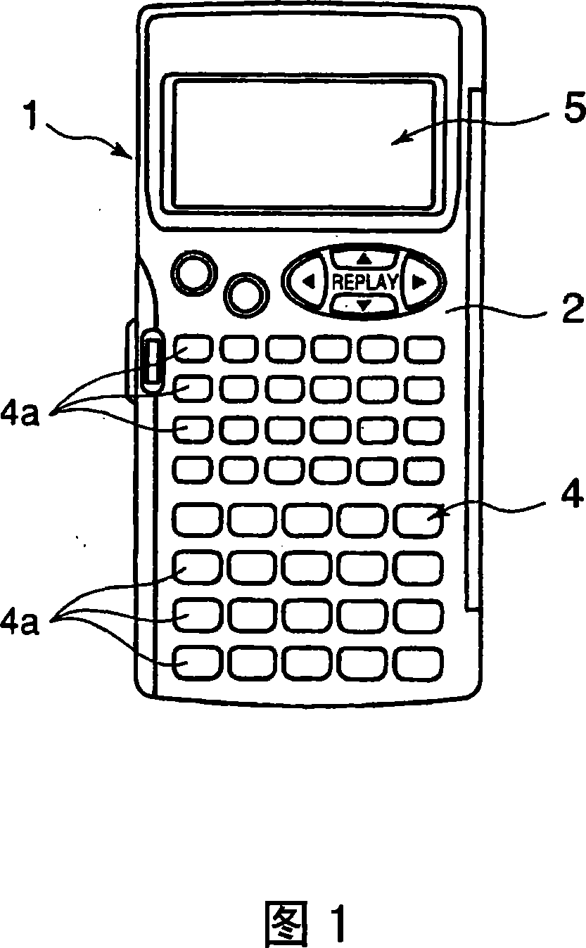
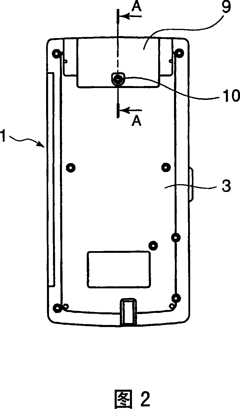
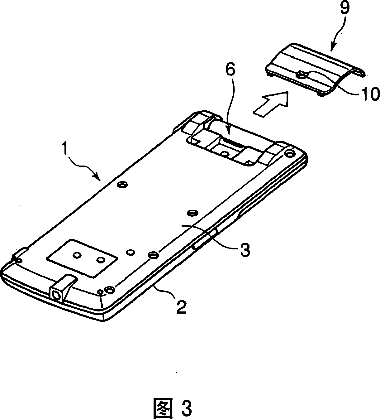
[0039] Fig. 1 is a front view of a small electronic calculator to which the present invention is applied, Fig. 2 is a back view of the small electronic calculator of Fig. 1, and Fig. 3 shows a state in which the battery cover of the small electronic calculator of Fig. 2 is removed An exploded perspective view of FIG. 4 is an enlarged sectional view of the main part viewed from the arrow A-A of FIG. 2 .

[0040] As shown in FIGS. 1 to 4 , the small electronic calculator includes a casing 1 .

[0041] The case 1 is composed of an upper case 2 and a lower case 3. In addition to setting a key input unit 4, a display unit 5, a battery accommodating unit 6, and a circuit board 7 (see FIG. 4 ), its interior also includes necessary components for computing functions. Various electronic components (not shown). ...

Embodiment approach 2

[0054] Next, Embodiment 2 in which the present invention is applied to an electronic compact calculator will be described with reference to FIGS. 14 to 17 . In addition, the same code|symbol will be used for the same part as Embodiment 1 shown in FIGS. 1-13 for description.

[0055] This electronic compact calculator is substantially the same as the first embodiment except that the metal plate 16 is not used and the shape of the screw 24 is different from the first embodiment.

[0056] That is, as shown in FIG. 15, the screw 24 has a first threaded portion 25 on the lower side, a second threaded portion 26 on the upper side, a detail 27 disposed between the first and second threaded portions 25, 26, and a head. Section 28. And, as shown in FIG. 14 , the first threaded portion 25 on the lower side is screwed into the threaded hole 12 of the nut 11 embedded in the lower case 3 , and the second threaded portion 26 on the upper side is screwed into the screw insertion hole 13 of ...

Embodiment approach 3

[0061] Next, Embodiment 3 in which the present invention is applied to an electronic compact calculator will be described with reference to FIGS. 18 to 21 . In this case, the same reference numerals will be used for the same parts as those in Embodiment 1 shown in FIGS. 1 to 13 .

[0062] Instead of the metal plate 16 of Embodiment 1, this electronic compact calculator is configured to include a spring member 30 that urges the screw member 10 in a direction away from the nut 11 of the lower case 3, and the structure is substantially the same as that of Embodiment 1 except that .

[0063] That is, as shown in FIG. 19( a ) and FIG. 19( b ), the spring member 30 is a coil spring having a substantially conical shape, and the lower end portion is formed into a coil spring having substantially the same size as the inner diameter of the countersink portion 14 of the battery cover 9 . portion, formed such that the inner diameter becomes gradually smaller toward the upper end portion ...


PUM


Abstract

An electronic apparatus is provided. The body shell is provided with a battery holding portion which can be installed with a battery cover for covering the battery holding portion. A bolt inserting hole is arranged in the battery cover to lead the bolt to insert into the hole and screw in the screw hole of the nut arranged in the lower shell of the body shell. A metal plate is fixed in the inner surface of the battery cover, in which a maintaining hole maintained by screwing a bolt. Therefore, even if releasing the bolt and separating away from the screw hole of the nut, the bolt can be further released and completely pulled out from the edge part of the screw hole of the nut by screwing the front end portion of the bolt in the maintaining hole of the metal plate. Thereby, the front end portion will not hitch the edge part of the screw hole of the nut to facilitate the battery cover to detach slidably.

Description

technical field [0001] The present invention relates to electronic devices having battery covers such as electronic small calculators (desktop electronic computers), electronic dictionaries, mobile phones, portable information processing terminals (PDA: Personal Digital Assistants), and game machines. Background technique [0002] In the past, a battery cover for a replaceable battery was provided in electronic equipment such as electronic calculators. For example, in the Japanese Patent Laid-Open Publication: JP-A-7-7278, it is described that a working battery accommodating portion and a supporting battery accommodating portion are set on the back of the casing, and the battery covers covering these battery accommodating portions can be opened respectively. Equipment closed to be mounted on the enclosure. In this case, since the frequency of battery replacement is high, the battery cover covering the working battery accommodating portion is slidably attached to the casing ...

Claims


Application Information

Patent Timeline
IPC IPC(8): H05K5/03H01M2/10
CPCY02E60/10
Inventor 西村雄一小根山涉日野冈孝
Owner CASIO COMPUTER CO LTD
Why Eureka
Try Eureka