
Rotational alignment femoral sizing guide

A sizing, femoral technology used in the field of sizing and rotational alignment devices to address issues such as lack of tool adjustment, inability to obtain accurate measurements, and increased surgical time

Active Publication Date: 2008-01-09
SMITH & NEPHEW INC
View PDF0 Cites 38 Cited by
  • Summary
  • Abstract
  • Description
  • Claims
  • Application Information

AI Technical Summary

Problems solved by technology

But these tools lack adjustment such that they can only involve one posterior condyle when they are rotated relative to anatomical landmarks
(Furthermore, exact measurements cannot be obtained as one condyle will protrude more than the other due to patient irregularities or diseased tissue or any other reason)
In other cases, these tools have additional parts that can be added to the tool to replace the condyle contacts, but the addition of these additional parts limits adaptability and increases surgical time because they need to be exchanged for Determining "Best Fit" Situations

Method used


Image

  • Rotational alignment femoral sizing guide
  • Rotational alignment femoral sizing guide
  • Rotational alignment femoral sizing guide

Examples


Embodiment Construction

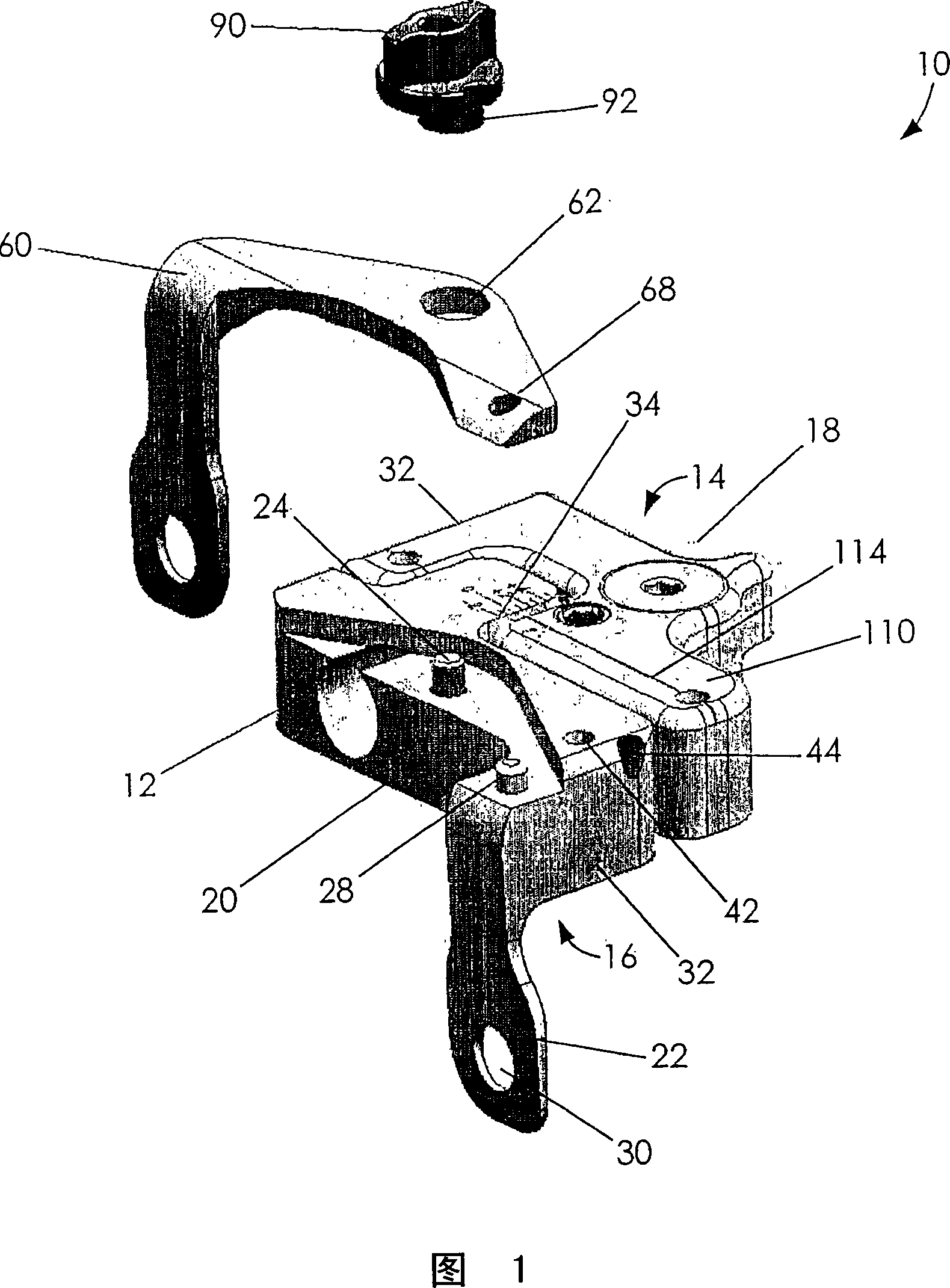
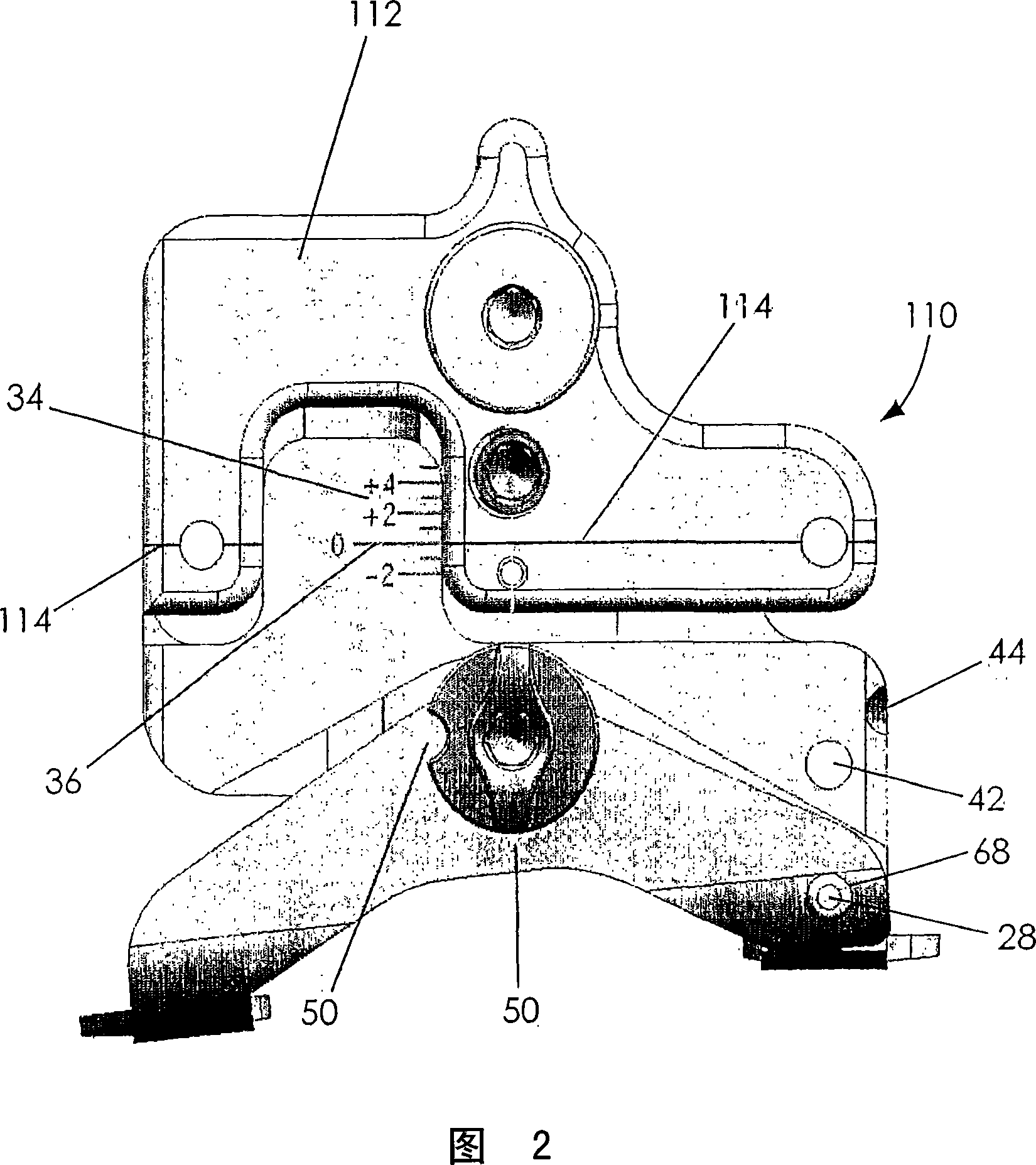
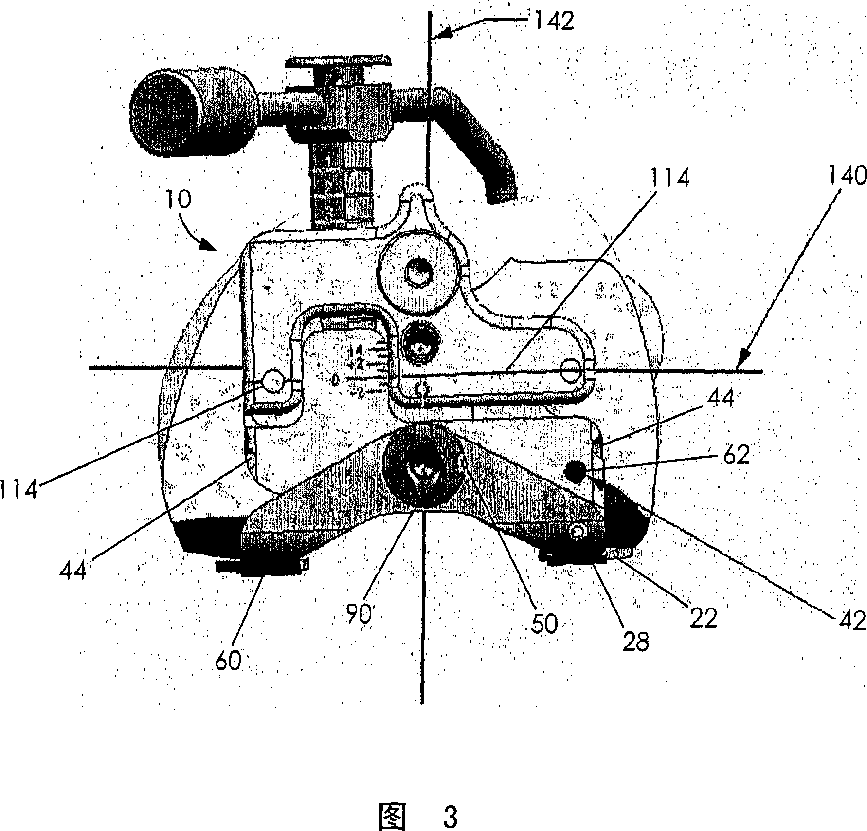
[0017] FIG. 1 shows body 12 , movable paddle 60 and rotary actuator 90 , generally referred to as assembly 10 . The body 12 is a block having an upper surface 14 , a lower surface 16 and a front 18 and rear 20 . (These anatomical orientations refer to when the main body 12 is in position on the distally resected femur.) Extending from the rear is a first paddle 22 . The paddle 22 is intended to provide a stable condylar reference point for the body 12 . The paddle 22 is also shown with a securing portion 30 intended to receive a securing pin, screw or any other securing mechanism to secure the paddle 22 in place. (While this first paddle 22 is provided in the preferred embodiment of the invention, it is not required for the assembly 10 to function as desired.)

[0018] The upper surface 14 of the body 12 has an actuator element 24 . The actuator element 24 is positioned toward the rear of the body and is substantially midway between the sides 32 of the body 12 . Although e...


PUM


Abstract

Embodiments of the present invention allow unlimited rotational alignment between two boundaries for alignment with anatomic landmarks while still referencing both posterior condyles for A / P sizing of the distal femur. In particular embodiments, the system provides at least one movable paddle that provides a reference point from the condyles so that the measuring assembly can be aligned to be parallel with the epicondylar axis. Once the measuring assembly is properly angled, the A / P length of the bone can then be measured from a proper reference point.

Description

[0001] This application submits on December 21, 2004 the U.S. provisional patent application No.60 / 638153 titled "Rotational Alignment Femoral Sizing Guide (rotational alignment femoral size measurement guide)" as priority, hereby The entire contents of this US provisional patent application are incorporated by reference. technical field [0002] The present invention relates to a sizing and rotational alignment device for determining anterior-posterior dimensions of the distal femur in order to determine proper implant size, and to methods of using such a device. Background technique [0003] In total knee replacement surgery, or arthroplasty, the knee joint is replaced with an artificial implant. The implant typically includes a tibial component, a femoral component, and a movable bearing insert (patella component). [0004] The inner surface of most femoral components has an intersecting plane that abuts the surgically prepared distal femoral surface. Its outer surface ...

Claims


Application Information

Patent Timeline
Patent Type & Authority Applications(China)
IPC IPC(8): A61B17/17A61B19/00A61F2/46
CPCA61B17/1764A61F2002/4658A61F2/4657A61B2019/467A61F2002/4668A61B2019/461A61F2/3859A61B2090/067A61B2090/061
Inventor R·R·小迪斯
Owner SMITH & NEPHEW INC
Learn More