Check patentability & draft patents in minutes with Patsnap Eureka AI!

Central test radio frequency system for emergency lighting

A technology for emergency lighting and testing systems, applied in instruments, alarms, etc., can solve problems such as system installation and maintenance defects, and achieve the effect of saving labor

Inactive Publication Date: 2011-10-12
BEGHELLI
View PDF4 Cites 0 Cited by
  • Summary
  • Abstract
  • Description
  • Claims
  • Application Information

AI Technical Summary

Problems solved by technology

[0005] However, since the emergency lighting unit of the known central testing system for emergency lighting communicates with the central control unit by means of wires or cables, it has serious drawbacks in terms of system installation and maintenance

Method used


Image

  • Central test radio frequency system for emergency lighting
  • Central test radio frequency system for emergency lighting
  • Central test radio frequency system for emergency lighting

Examples


Embodiment Construction

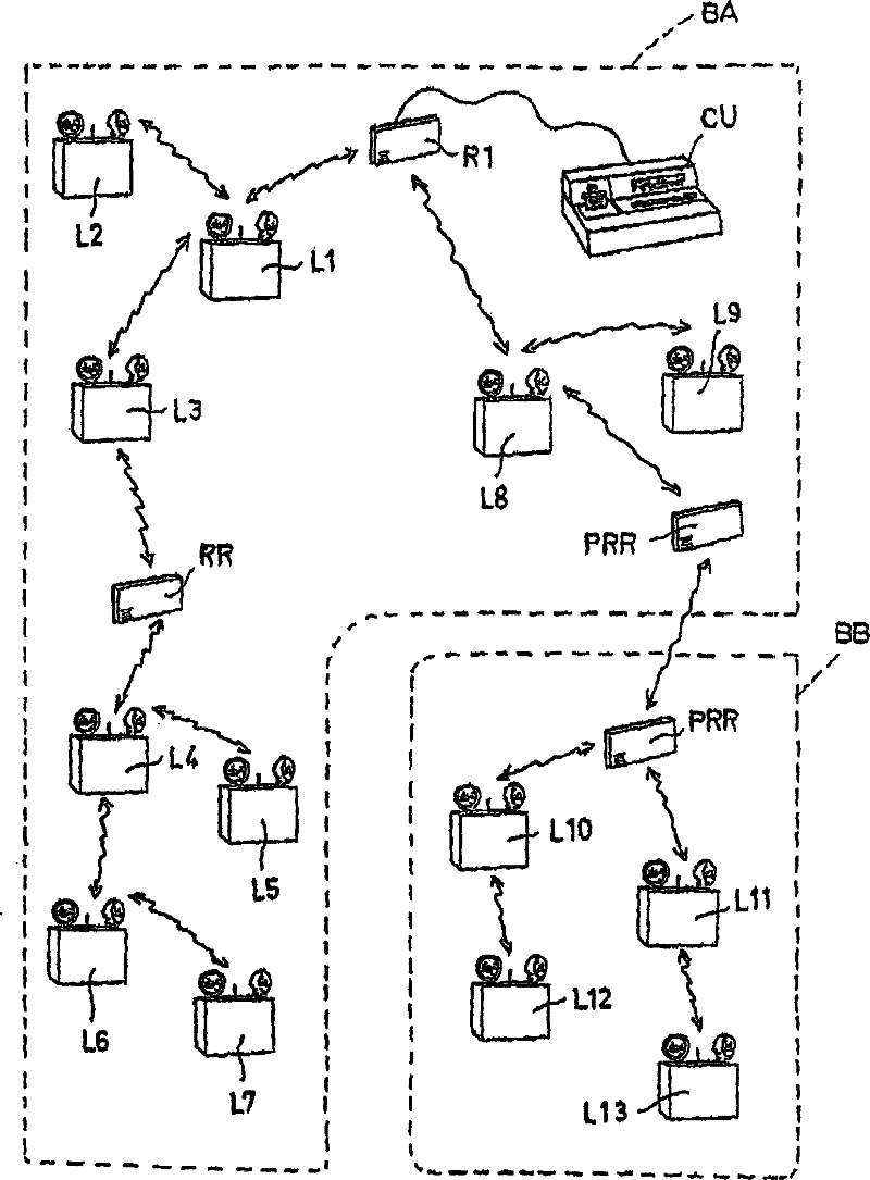
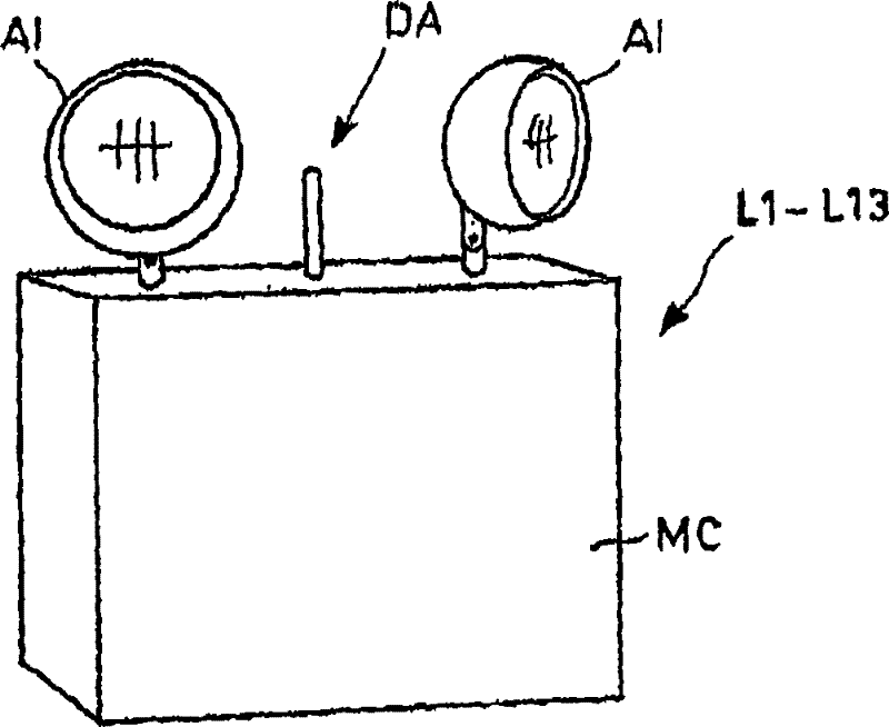
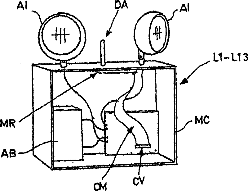
[0023] refer to Figure 1-3 , figure 1 The central test radio frequency system for emergency lighting (referred to as the "CTRF" system) of ® enables testing of emergency lighting units L1-L13 in one or more buildings BA, BB from a single location.

[0024] The CTRF system is a completely wireless system for device communication by means of radio frequency signals.

[0025] The CTRF system consists of a group of said emergency lighting units L1-L13 (hereinafter also referred to as emergency lights) scattered in buildings BA, BB and a remote control unit CU that manages the functionality of said system; each emergency lighting Units L1-L13 are typically powered by the mains.

[0026] The emergency lights L1-L13 communicate with each other via radio signals.

[0027] Each emergency lighting unit L1-L13 is used as a repeater;

[0028] When the control unit CU needs to send or receive information to / from a specific emergency light L1-L13, it only reaches that emergency lightin...


PUM


Abstract

A central test radio frequency system for emergency lighting comprising a set of emergency light units or (CU) that manages the system's functionality, wherein each of said emergency lamps (LI-L13) has a radio transmitter-receiver (MR), which is able to communicate to each other emergency lamps and to the remote control unit (CU) via radio signals.

Description

technical field [0001] The present invention relates to a central test radio frequency system for emergency lighting. [0002] More specifically, the invention relates to an emergency lighting system comprising a group of emergency lighting units or lights communicating with each other via radio signals. Background technique [0003] Emergency lighting systems are known which comprise a set of emergency lights, each of which has an automatic test device for controlling the corrective functionality; in this case, each emergency lighting unit incorporates Battery test function and lamp test function. [0004] Emergency lighting systems (so-called central testing systems) are also known in which a central unit receives test information and an operator can send commands to each emergency light in order to synchronize the testing process and configure the emergency lighting units. [0005] However, since the emergency lighting units of known central testing systems for emergenc...

Claims


Application Information

Patent Timeline
Patent Type & Authority Patents(China)
IPC IPC(8): G08B25/10
Inventor 吉安·彼德罗·贝格利
Owner BEGHELLI
Features
  • R&D
  • Intellectual Property
  • Life Sciences
  • Materials
  • Tech Scout
  • Unparalleled Data Quality
  • Higher Quality Content
  • 60% Fewer Hallucinations
Learn More