Brake block mechanism for dry skating boot deflection brake

A technology for brake pads and roller skates, which is applied to roller skates, ice skating, and skateboards. It can solve the problems of not having a unidirectional braking function, affecting the safety of roller skates, and insufficient braking force, so as to achieve reliable braking action. Easy installation and simple brake mechanism

Inactive Publication Date: 2008-01-16
林苏钦
View PDF1 Cites 2 Cited by
  • Summary
  • Abstract
  • Description
  • Claims
  • Application Information

AI Technical Summary

Problems solved by technology

In 2005, the applicant of the present invention applied for a "Roller Skates Utilizing the Swing Brake of the Shoe Wheel Support" (the application number is 200510022023.3). There is a brake mechanism that brakes with the deflection of the shoe wheel bracket. The brake mechanism is composed of a brake link that is movably connected to the shoe wheel bracket, a brake block that is connected to the brake link, and the top member of the link and the brake link. Although the brake mechanism has the effect of braking, its structure is relatively complicated, and the brake block only contacts the side of the shoe wheel, the braking force is insufficient and does not have a unidirectional braking function, which affects the safety of the entire roller skates

Method used


Image

  • Brake block mechanism for dry skating boot deflection brake
  • Brake block mechanism for dry skating boot deflection brake
  • Brake block mechanism for dry skating boot deflection brake

Examples


Embodiment 1

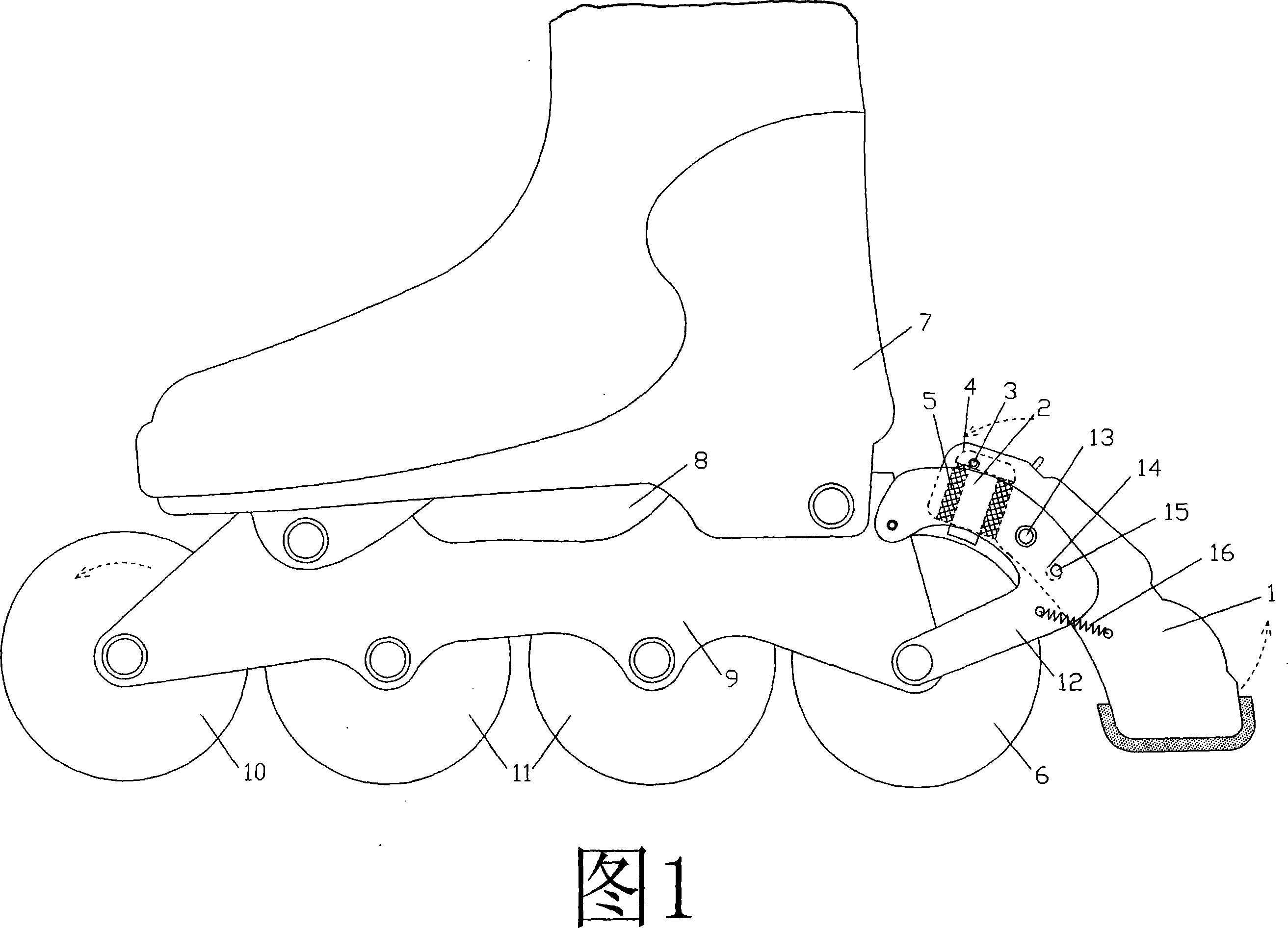
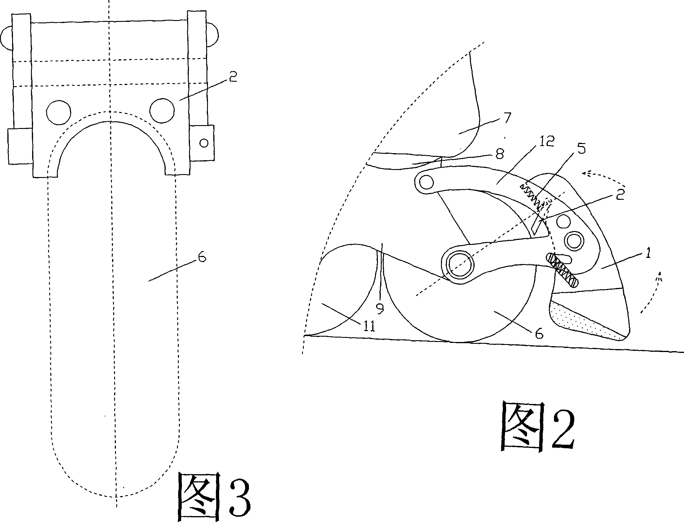
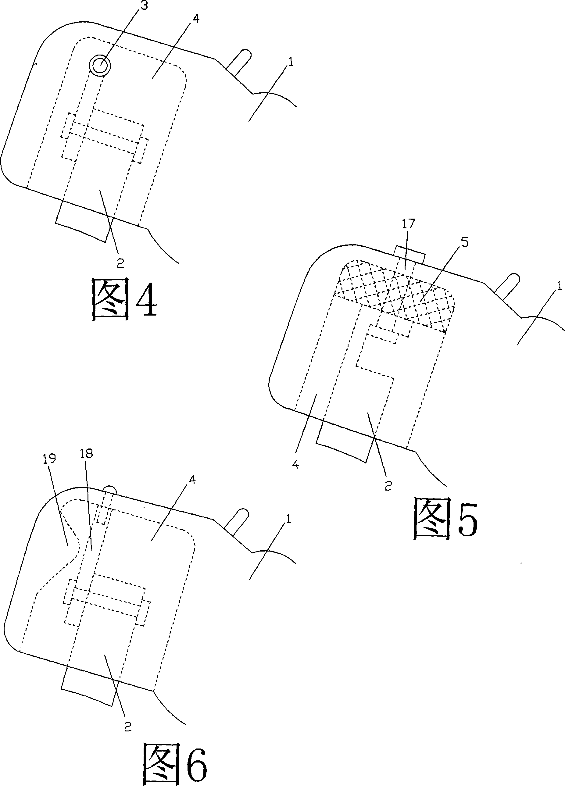
[0025] Example 1. The structure of the brake pad of this embodiment is shown in FIG. 1 , which has a brake pad 2 connected to the rear brake swing block 1 that can be contacted and deflected. Specifically, the brake pad 2 is movably connected to the groove on the brake swing block through the connecting shaft 3 4, the left and right sides of the brake pad are embedded with elastic bodies 5 that can limit the swing of the brake pad in the groove; the elastic body 5 can also be one, located on the left side of the brake pad (see Figure 2); The body 5 constitutes the swing restricting member of the brake pad, and the elastic body can also adopt a spring structure; the braking surface of the brake pad is a contact wheel surface with a substantially smooth surface and can fit the surface of the outer upper half of the wheel of the shoe wheel 6 (see Figure 3), the brake pad 2 is in contact with the shoe wheel 6 as the brake swing block 1 touches the ground and deflects; the brake pa...

Embodiment 2

[0027] Example 2. The structure of the brake pad of this embodiment is shown in FIG. 7 , with the brake pad 2 connected to the front and rear extension brake brackets 21 of the sole shell 8 and / or the sole center column 20. The brake pad 2 is long and has a certain elasticity. The plate can be deflected with the front and rear shoe wheel brackets 9a, 9b to contact with the front and rear shoe wheels 10, 6; (i.e. front) upper part of the wheel surface or the outer (i.e. rear) upper part of the wheel surface of the rear shoe wheel 6 fits the contact wheel surface (refer to FIG. 3), the front wheel 10 alone pushes hard on the ground to cause the front shoe wheel bracket After the deflection, the brake pad 2 is in contact with the surface of the front wheel. At this time, when the front wheel 10 touches the ground and rotates backward (clockwise), the brake pad is driven to shift backward, and the braking surface will directly sink into the soft surface of the shoe wheel. , And t...

Embodiment 3

[0030] Example 3. This embodiment is shown in Fig. 8. The biggest difference between the structure shown in Fig. 8 and Fig. 7 is: the shoe wheel bracket 9 in Fig. 8 is a whole, and the shoe wheel bracket 9 is movably connected to the sole shell through the front and rear connecting pieces 22. On the corresponding central column 20 above, the connecting piece 22 is composed of a connecting shaft, a sleeve sleeved outside the connecting shaft and a connecting nut. The left and right two pieces are fixedly locked at the two ends of the sleeve, and the shoe wheel bracket 9 can be rotated; 34 in the figure is a locking rod. Of course, the same brake pad mechanism as in Embodiment 2 can be used completely in FIG. 8 .


PUM


Abstract

The invention discloses a brake block mechanism used for the deviated brake of the roller skates, which has a brake block that can be connected to the brake swing block which can deviate when touching the ground, the invention is characterized in that the brake swing block is provided with a brake block swing-limit member, the brake block can deviate following the brake swing block or the wheel stent to touch the shoe wheel; the brake surface of the brake block is a wheel-touching surface with a basic smooth surface that can couple with the surface of the wheel at the outer upper half part of the shoe wheel, the brake block can rotate following the shoe wheel after touching the wheel to do deviated brake. The brake block of the invention directly enforce unidirectional brake to the soft surface of the shoe wheel, such effect is favorable for improving the safety of the sliding, and the roller skates can play the role of anti-falling forward and backward, and is particularly suitable for beginners to use for learning sliding.

Description

Technical field [0001] The invention relates to a brake pad mechanism for realizing one-way braking of roller skates by means of the deflection of a brake swing block or a shoe wheel bracket. Background technique [0002] At present, most of the roller skates on the market have a braking device that is a brake block fixed on the wheel bracket, which mainly relies on the friction between the brake block and the ground to achieve the purpose of braking. In 2005, the applicant of the present invention applied for a kind of "roller skates using shoe wheel brackets to swing and brake" (application number 200510022023.3). This technology divides the shoe wheel brackets into front and rear shoe wheel brackets, and in the two shoe wheel brackets The brake mechanism is provided with a brake mechanism that brakes with the deflection of the shoe wheel bracket. The brake mechanism is composed of a brake link movably connected to the shoe wheel bracket, a brake block connected to the bra...

Claims


Application Information

Patent Timeline
Patent Type & Authority Applications(China)
IPC IPC(8): A63C17/14A63C17/06
CPCA63C17/1418A63C17/1445A63C17/06A63C17/1409
Inventor 孙群
Owner 林苏钦
Why Eureka
Try Eureka