UPS system and method for remote monitoring

A remote monitoring and remote technology, applied in the field of UPS systems, can solve problems such as failure to meet application requirements, remote monitoring, property power interruptions, etc., and achieve good application prospects and convenient remote monitoring.

Active Publication Date: 2010-09-01
BEIJING LIANDONG TIANYI TECH
View PDF3 Cites 0 Cited by
  • Summary
  • Abstract
  • Description
  • Claims
  • Application Information

AI Technical Summary

Problems solved by technology

Most of these access layer devices are located in unattended weak current shafts. The current power consumption environment of these shafts has the following problems: urban power consumption is tight, and power cuts by region lead to temporary and property power interruptions; power maintenance or grid failures will Service interruption; unstable power supply in urban-rural fringe areas and rural areas, and remote maintenance is difficult; power outages cannot be known at the first time, and cannot be coordinated and remedied in time
Most of the terminal access layer devices of the telecommunication network are located in unattended weak current shafts, and the above two types of UPS cannot meet their application requirements
Moreover, almost all of the above two types of UPS use lead-acid batteries as backup batteries, and there are problems such as large size, heavy weight, environmental protection, regular battery maintenance, and inability to monitor remotely.

Method used


Image

  • UPS system and method for remote monitoring
  • UPS system and method for remote monitoring
  • UPS system and method for remote monitoring

Examples


Embodiment 1

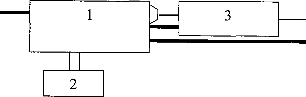
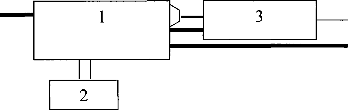
[0016] Such as figure 1 Described, described UPS system comprises UPS main board 1, lithium battery 2, interface conversion module 3, described lithium battery 2 is connected with UPS main board 1 charging and discharging circuit by wire, UPS main board 1 links with conversion interface module 3 to realize and Communication of remote centralized monitoring platform. The interface conversion module 3 is for converting the RS232 interface of the UPS mainboard into an RJ45 interface to facilitate the connection of the UPS system in the present invention with the remote centralized monitoring platform with a network cable. The UPS mainboard 1 can be a mainstream 500VA mainboard, and the lithium battery 2 can be a 3.7V 5AH battery. In this embodiment, the UPS mainboard 1 is also responsible for collecting information such as load, input and output, and battery power, and communicates with the remote centralized monitoring platform through the TCP protocol to realize remote monitor...

Embodiment 2

[0028] The device and method used in this embodiment are all the same as embodiment one, only difference is: described interface conversion module 3 is that the RS232 interface of UPS main board is converted into GPRS or CDMA wireless data interface to facilitate UPS among the present invention The system is connected to the remote centralized monitoring platform.

Embodiment 3

[0030] The device and method used in the present embodiment are all the same as embodiment one, only difference is: described interface conversion module 3 is to convert the RS232 interface of UPS main board into short message air interface to facilitate the UPS system among the utility model and Remote centralized monitoring platform connection.

[0031] The above embodiments can solve various problems of traditional small lead-acid battery UPS in the unattended environment at the end of the telecommunication network, and the UPS system in the present invention can communicate with the mainstream centralized monitoring platform of the current telecommunication network, which can be convenient Realize remote monitoring.


PUM


Abstract

The invention provides a UPS system and a method of remote monitor and can be applied to telecommunication end interposed layer equipment with low power. In the system, a centralized monitor platform can monitor the UPS work state, with the advantages of small volume, light weight, no pollution and no need of regular maintenance. The UPS system provided by the invention includes a UPS mainboard, a storage battery, and an interface conversion module. The storage battery protection panel is connected with the UPS mainboard charge and discharge circuit by wires. The UPS mainboard is communicatedwith a remote centralized monitor platform by a conversion interface module. The method disclosed in the invention can finish the program order solidified in the UPS mainboard.

Description

technical field [0001] The invention relates to a UPS system and method capable of remote monitoring, which are mainly applied to low-power telecommunication terminal access layer equipment. Background technique [0002] With the continuous pursuit of service quality by telecom operators, when providing services such as broadband access, PHS access, and future 3G access to users, it is necessary to ensure that the terminal equipment does not provide services in the event of unstable mains power or power outages. interruption. Most of these access layer devices are located in unattended weak current shafts. The current power consumption environment of these shafts has the following problems: urban power consumption is tight, and power cuts by region lead to temporary and property power interruptions; power maintenance or grid failures will Cause service interruption; the urban-rural fringe area and rural areas have unstable power supply, and remote maintenance is difficult; ...

Claims


Application Information

Patent Timeline
Patent Type & Authority Patents(China)
IPC IPC(8): H04M11/00G08C17/02H02J7/00
Inventor 朱鸿江
Owner BEIJING LIANDONG TIANYI TECH
Why Eureka
Try Eureka