Supercharge Your Innovation With Domain-Expert AI Agents!

Multi-view display device

A display device, multi-view technology, used in image communication, static indicators, optics, etc.

Inactive Publication Date: 2008-01-16
KONINKLIJKE PHILIPS ELECTRONICS NV
View PDF3 Cites 3 Cited by
  • Summary
  • Abstract
  • Description
  • Claims
  • Application Information

AI Technical Summary

Problems solved by technology

Although the image quality of the multi-view display device controlled based on the method described in WO 99 / 05559 is relatively good, there is still room for improvement

Method used


Image

  • Multi-view display device
  • Multi-view display device
  • Multi-view display device

Examples


Embodiment Construction

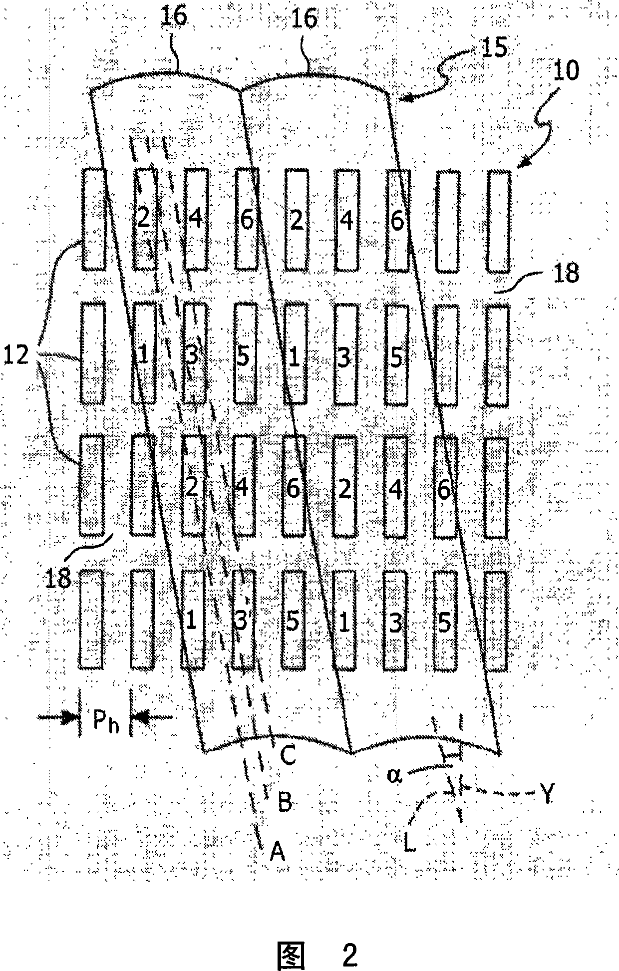
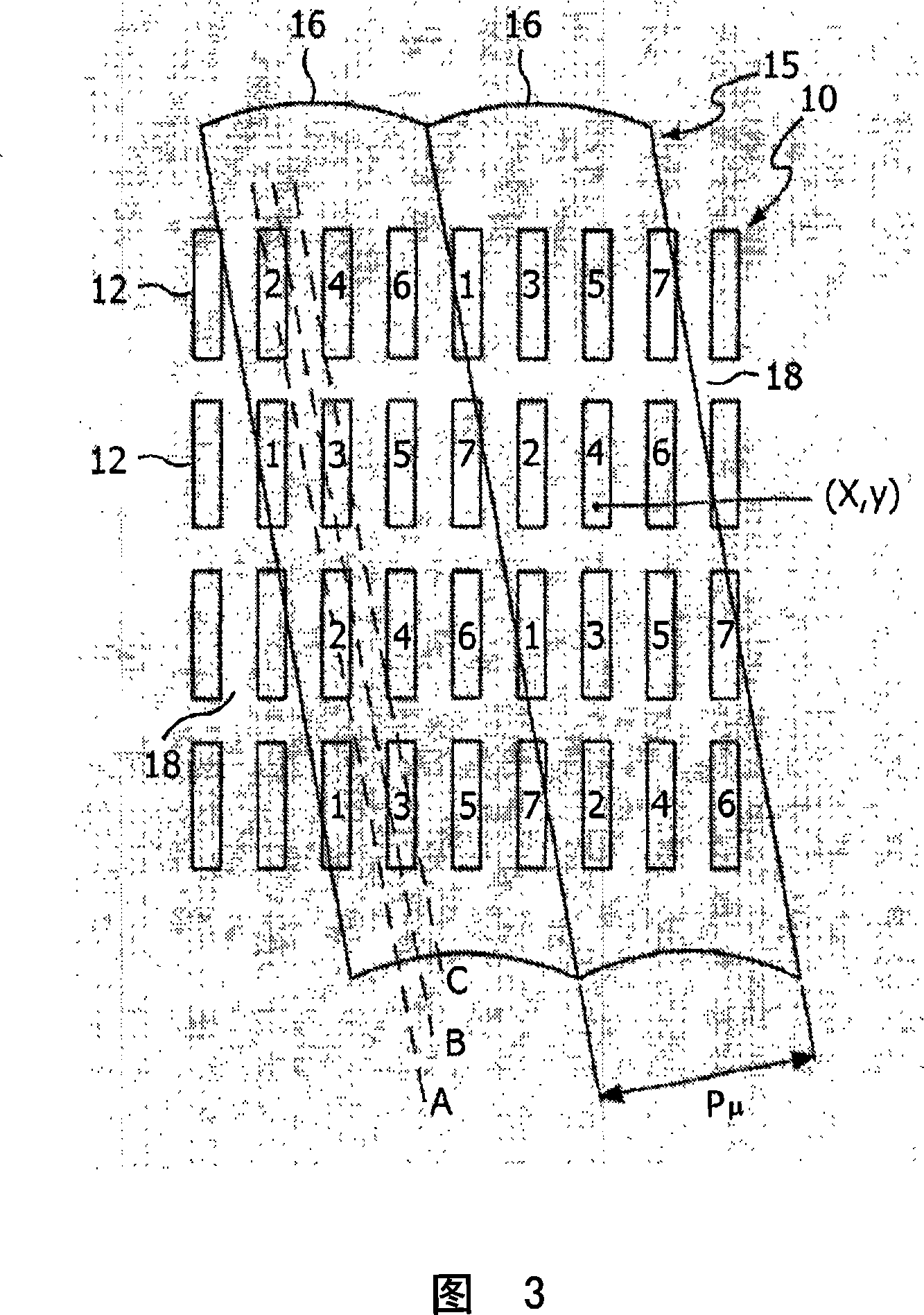
[0038] In the following examples, a direct-view 3D-LCD lenticular lens array display device 100 with a lenticular tilting structure is first described with reference to FIGS. 1 to 3 in order to illustrate the present invention.

[0039] It should be understood that the drawings are merely schematic and not drawn to scale. Some dimensions may have been exaggerated, while other dimensions may have been reduced, for clarity of illustration. In addition, the same reference numerals and letters are used throughout the drawings to refer to the same parts and dimensions, where appropriate.

[0040] Referring to Figure 1, a display device 100 comprises a conventional LC matrix display panel 10 which acts as a spatial light modulator and comprises individually addressable and similarly sized light generating elements 12 arranged in aligned rows and columns perpendicular to each other. planar array. Although only a few light generating elements are shown, in practice there may be appr...


PUM


Abstract

A multi-view display device (100) is disclosed . The multi-view display device comprises: a structure of light-generating elements (10); a structure of optical means (15) for directing light being generated by the structure of light-generating elements (10) in a number of directions corresponding to respective views; and computing means (18) for computing luminance values for the respective light-generating elements on basis of an input signal (414), whereby for the computation of a particular luminance value (420) for a particular light-generating element (402), the computing means (18) is arranged to take into account a spatial displacement between a first location (412) of the particular light-generating element (402) and a second location (410) of the corresponding one of the optical means (408).

Description

technical field [0001] The present invention relates to a multi-view display device, which includes: [0002] - light generating element structure; and [0003] - An optical device structure for directing light generated by the light generating element structure in a plurality of directions corresponding to respective views. [0004] The invention further relates to a method for calculating brightness values ​​for individual light generating elements in such a multi-view display device. [0005] The invention further relates to an image processing arrangement for calculating brightness values ​​for individual light generating elements in such a multi-view display device. Background technique [0006] Since the introduction of display devices, realistic 3D display devices have become the dream of many people. Many principles leading to such display devices have been investigated. Some principles try to create realistic 3D objects in a certain volume. For example, in a di...

Claims


Application Information

Patent Timeline
Patent Type & Authority Applications(China)
IPC IPC(8): G09G3/20G02B30/27
CPCH04N13/0447H04N13/0404G02B27/2214H04N13/0415H04N13/305H04N13/317H04N13/351G02B30/27
Inventor R·-P·M·伯雷蒂F·J·彼得斯
Owner KONINKLIJKE PHILIPS ELECTRONICS NV
Features
  • R&D
  • Intellectual Property
  • Life Sciences
  • Materials
  • Tech Scout
  • Unparalleled Data Quality
  • Higher Quality Content
  • 60% Fewer Hallucinations
Learn More