Dust collecting unit of vacuum cleaner

A technology for vacuum cleaners and dust collection, which is applied in the directions of vacuum cleaners, suction filters, cleaning equipment, etc., can solve the problem of low air purification ability, and achieve the effect of improving air purification ability

Inactive Publication Date: 2008-01-23
LG ELECTRONICS (TIANJIN) APPLIANCES CO LTD
View PDF0 Cites 53 Cited by
  • Summary
  • Abstract
  • Description
  • Claims
  • Application Information

AI Technical Summary

Problems solved by technology

[0017] But, the vacuum cleaner of prior art, because the foreign matter in the air only filters

Method used


Image

  • Dust collecting unit of vacuum cleaner
  • Dust collecting unit of vacuum cleaner
  • Dust collecting unit of vacuum cleaner

Examples


Embodiment Construction

[0050] Below, the embodiments of the present invention will be described in detail with reference to the accompanying drawings.

[0051] The present invention provides a dust collection unit of a vacuum cleaner. The dust collection unit of the vacuum cleaner mainly includes: a first cyclone device 240 for filtering foreign matter in the air for the first time, and a first cyclone device 240 for filtering foreign matter in the air passing through the first cyclone device 240 The second cyclone device 250 for secondary filtration and the dust collection cylinder 210 with more than 3 dust collection chambers 248, 256, 260 for separating and collecting foreign matter in the air; for covering the upper cover 220 above the dust collection cylinder 210; The bottom cover 230 of the bottom of the dust container 210 .

[0052] The first cyclone device 240 includes: a guide cylinder 242 with a diameter smaller than the dust collection cylinder 210 to guide the air flow, and a first dust ...


PUM


Abstract

The invention discloses a dust collecting unit of vacuum cleaner, which mainly comprises a first cyclone device for filtering the foreign bodies in air for first time, a second cyclone device used for filtering the foreign bodies in air passing through the first cyclone device for the second time, over three dust collecting cylinders of dust collecting chambers used for separating foreign bodies in the air collected, an upper surface cover used for covering the upper surface of the dust collecting cylinder and a lower surface cover used for covering the lower surface of the dust collecting cylinder. The invention has the advantages that: the foreign bodies in air absorbed from outside in the vacuum cleaner are double filtered through the flow of the cyclone, therefore, is can enhance the air purify capacity of the vacuum cleaner, namely the filtering capacity. The invention has three dust collecting chambers to collect the foreign bodies in air, thus the foreign bodies will be separated gradually, which improves the filtering efficiency; besides, the dust collecting cylinder is made of transparent material, which enables users conveniently confirm the foreign bodies quantity collected without needing to separating the dust collecting unit out from the cleaner body.

Description

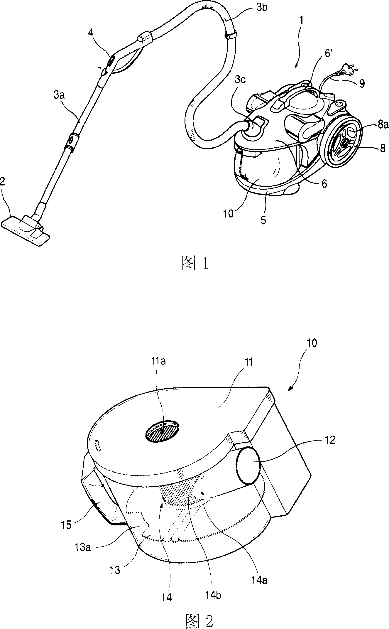
technical field [0001] The invention relates to a vacuum cleaner, in particular to a dust collection unit of the vacuum cleaner equipped with several cyclone devices capable of gradually separating foreign objects in the air and a dust collection cavity. Background technique [0002] Figure 1 is a perspective view of a prior art vacuum cleaner. As shown in the figure, the vacuum cleaner includes: a body 1 with a suction device for absorbing indoor air inside; a suction nozzle 2 for sucking air near the ground by using the suction force generated by the body 1 . [0003] Described fuselage 1 comprises: the lower fuselage 5 that suction device is installed; Prevent the parts inside the lower fuselage 5 from being exposed to the outside, and the upper fuselage 6 that controls the vacuum cleaner electric control unit (not shown) is arranged inside. [0004] On the top of the upper body 6, there is a moving handle 6 ′ protruding circularly upwards. When the vacuum cleaner is mo...

Claims


Application Information

Patent Timeline
IPC IPC(8): A47L9/16A47L9/00
Inventor 朴大焕徐宗玄黄弼载梁炳善金圣根
Owner LG ELECTRONICS (TIANJIN) APPLIANCES CO LTD
Why Eureka
Try Eureka