Master-salve equipment switch control method

A control method and equipment technology, applied in the direction of digital transmission system, electrical components, error prevention, etc., can solve the problems of wrong switching, no research and mention of communication between the control device and the controlled device, and no consideration of normal communication, etc. Achieve the effect of avoiding false switching and perfecting the redundant switching control mechanism

Inactive Publication Date: 2010-05-19
ASAT CHINA TECH
View PDF2 Cites 2 Cited by
  • Summary
  • Abstract
  • Description
  • Claims
  • Application Information

AI Technical Summary

Problems solved by technology

In the above redundant switching control method, the main basis for deciding whether to perform switching operations is to judge the state signals of the two control devices. These state signals only indicate their own operating conditions, and whether the control device and the controlled device are Normal communication is also not considered, and there is no research and mention on how to judge and identify whether the communication between the control device and the controlled device is normal. For the redundant system master-slave equipment switching control method, between the control device and the controlled device Whether the communication is normal or not is the final and most important factor to consider whether switching is required; at the same time, the above status signal is transmitted through the signal line connected between the two control devices. If the signal line fails, the connection between the two control devices There will be problems in the status signal transmission between them, so there will be two results: the first is that the backup control device does not respond after receiving the status signal from the main control device, and the second is that the backup control device cannot receive the status signal from the main control device. Switching is automatically started after the status signal, so it is easy to cause accidental switching

Method used


Image

  • Master-salve equipment switch control method
  • Master-salve equipment switch control method
  • Master-salve equipment switch control method

Examples


Embodiment Construction

[0040] The present invention will be further described in detail below in conjunction with the accompanying drawings and embodiments.

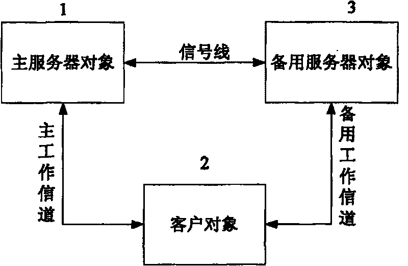
[0041] figure 1 In the shown redundant system, there are running main server object 1, client object 2, standby server object 3 with the same configuration as the main server object, the main working channel connecting the main server object and the client object, and connecting the standby server The standby working channel between the object and the client object; the main server object is connected with the standby server object through a monitorable communication connection; the monitorable communication connection can be a network communication mode or a serial communication mode.

[0042] The main server object and the standby server object are connected through a signal line, and a real-time communication mechanism is established between the standby server object and the main server object through the signal line, and the main server ob...


PUM


Abstract

The present invention relates to a controlling method for the switch between a principal device and a subordinate device in a redundant system, which at least comprises a principal server object, a client object, a standby server object, a principal working channel connected between the principal server object and the client object and a standby working channel connected between the standby serverobject and the client object. The principal server object is connected with the standby server object through a monitoring communication connecting manner. The present invention is characterized in that: when the principal and standby server communicates normally, the principal server object transmits initiatively an switching control order to start the switch between the principal device and subordinate device according to the fault signal of principal working channel running state; when the principal server object and the standby server object communicates unsuccessfully, the standby working channel starts the switch between the principal device and subordinate device according to the fault signal of monitoring principal working channel running state. Compared with the prior art, when the judgment that whether to switch the principal and subordinate device is made, the present invention not only considers the running states of both the principal server object and the principal working channel but also provides a method for judging the self running state of the principal server object and the running state of the principal working channel. Compared with the prior art, the presentinvention is a redundancy switching controlling mechanism which is safer and more perfect.

Description

technical field [0001] The invention relates to a switching control method for working between devices, in particular to a switching control method for master-slave devices in a redundant system. Background technique [0002] In the field of industrial automation, in order to improve the reliability of the system, the functional components that play a key role in the continuous operation of the system are generally redundantly configured, and the spare components of the redundant configuration will adopt the same configuration as the main operating components to reduce risks. , increasing the reliability of the system. The function of the redundant configuration is to take over the internal information by using the backup parts and use the backup system as a new operation system when the main operation part fails or needs to be replaced or the internal operation system of the main operation part needs to be updated and upgraded. , allowing the system to continue running wit...

Claims


Application Information

Patent Timeline
Patent Type & Authority Patents(China)
IPC IPC(8): H04L1/22H04B1/74
Inventor 梁俊林苑
Owner ASAT CHINA TECH
Why Eureka
Try Eureka