
Crossover circuit for reducing impedance response variance of a speaker

A frequency division circuit and impedance response technology, which can be used in the field where one frequency is louder and another frequency is louder, and can solve problems such as impedance fluctuations

Inactive Publication Date: 2008-02-13
APERION AUDIO
View PDF0 Cites 5 Cited by
  • Summary
  • Abstract
  • Description
  • Claims
  • Application Information

AI Technical Summary

Problems solved by technology

[0004] However, combining a divider circuit with a driver creates an impedance that fluctuates significantly as a function of frequency

Method used


Image

  • Crossover circuit for reducing impedance response variance of a speaker
  • Crossover circuit for reducing impedance response variance of a speaker
  • Crossover circuit for reducing impedance response variance of a speaker

Examples


Embodiment Construction

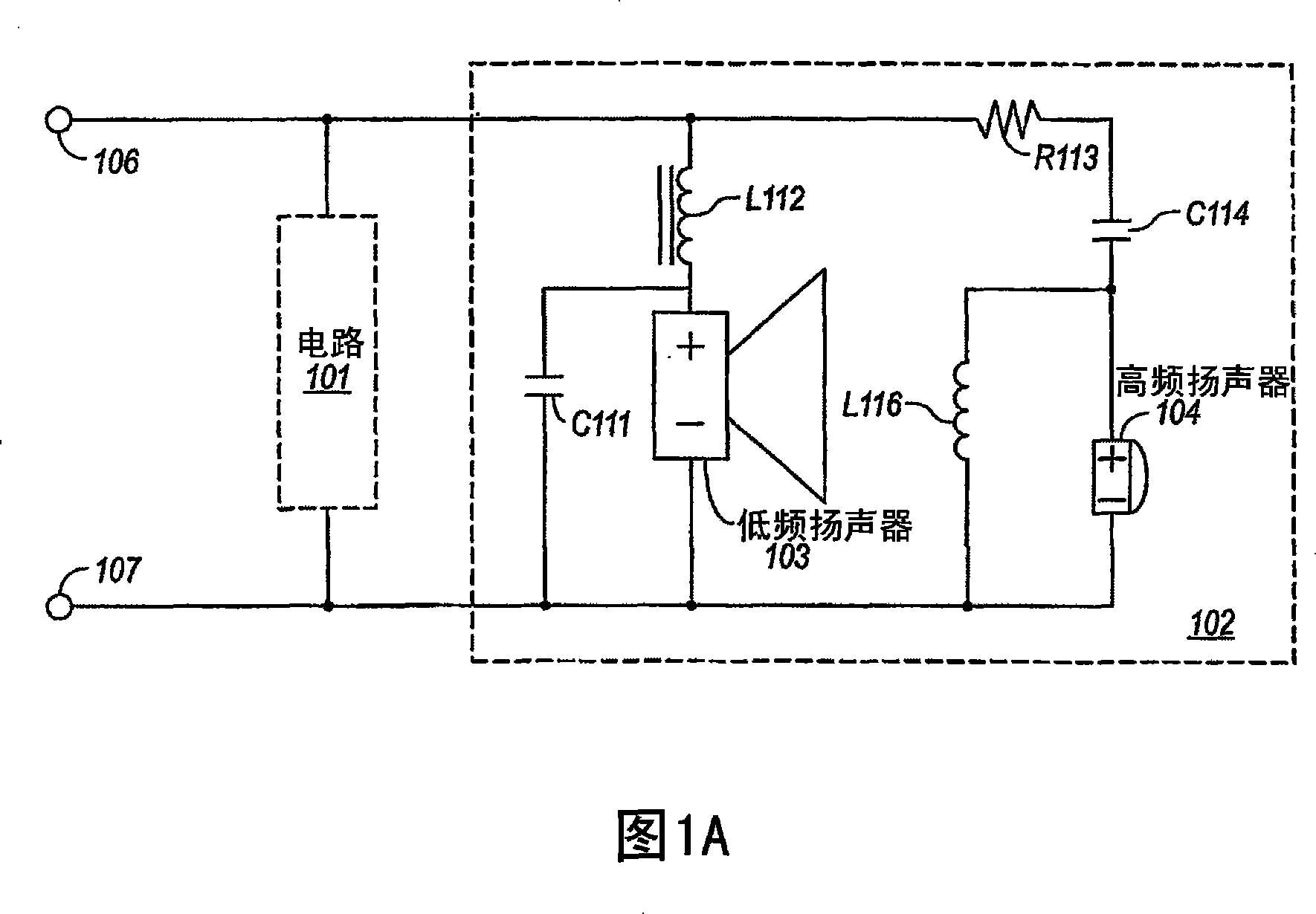
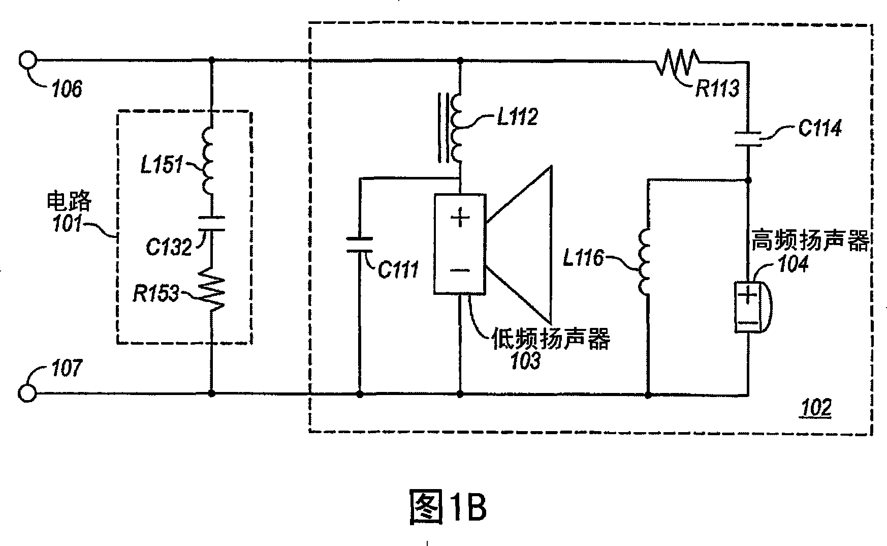
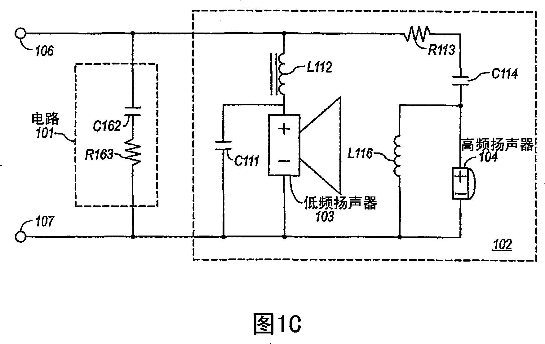
[0014] Embodiments of the present invention relate to crossover circuits for reducing deviations in the impedance response of loudspeakers. A speaker includes at least one driver and one or more electronic components. A speaker has a baseline impedance and frequency response when there is no associated series resistance or impedance connected to the speaker. Connect the speaker to external components with terminal pairs. Connecting a speaker to external components creates an associated series resistance or impedance that causes the speaker's frequency response to differ from the baseline frequency response. A frequency dividing circuit is connected to at least one terminal of the aforementioned pair of input terminals. The frequency divider circuit includes electronic components configured to reduce deviations in frequency response due to connection of external components.

[0015] For example, FIG. 1 shows a crossover circuit 101 for reducing the impedance response deviati...


PUM


Abstract

Embodiments of the present invention are directed to crossover circuits for reducing impedance response variance of a speaker. A speaker includes at least one driver and one or more electrical components. The speaker has a baseline frequency and impedance response when no associated series resistance or impedance is connected to the speaker. A pair of terminals is used for connecting the speaker to external components. Connecting the speaker to external components results in an associated series resistance or impedance, that causes the frequency response of the speaker to vary from the baseline frequency response across various frequency ranges. A crossover circuit is connected to at least one of the pair of input terminals. The crossover circuit includes electrical components configured to reduce the impedance response variance inherent to the speaker, thus reducing variances in the frequency response caused by impedances and resistances placed in series with the speaker.

Description

[0001] Cross References to Related Applications [0002] This application claims priority to U.S. Provisional Patent Application Serial No. 60 / 629,627, entitled "crossover circuit," filed November 18, 2004, which is hereby incorporated by reference in its entirety . This application also requires a U.S. utility model patent with an unknown serial number, filed on November 16, 2005, entitled "Crossover Circuit For Reducing Impedance Response Variance of aSpeaker (a frequency division circuit for reducing speaker impedance response deviation)" Priority of the application, the entirety of which is hereby incorporated by reference. Background technique [0003] Many loudspeakers include a "crossover circuit," an electronic network of capacitors, resistors, and / or inductors. Crossover circuits divide the wide audio frequency spectrum into finite bandwidths suitable for individual frequency-specific drivers (woofer, midrange, tweeter, etc.). The crossover circuit also equalizes t...

Claims


Application Information

Patent Timeline
Patent Type & Authority Applications(China)
IPC IPC(8): H04R3/00
Inventor 肯尼斯·H.·汉弗莱斯
Owner APERION AUDIO
Learn More