
Resonant sensor probe assembly

a technology of resonant sensor and probe body, which is applied in the direction of instruments, material impedance, transportation and packaging, etc., can solve the problems of low sensitivity, little to no resolution between different effects on oil, and embolism of subject matter described

Pending Publication Date: 2022-10-13
GE GLOBAL SOURCING LLC
View PDF4 Cites 2 Cited by
  • Summary
  • Abstract
  • Description
  • Claims
  • Application Information

AI Technical Summary

Benefits of technology

The patent is about a resonant sensor probe assembly for detecting impurities in fuel used in engines. The assembly includes a substrate, free-standing electrodes, and a controller. The electrodes are placed in the fuel and an electric field is generated between them to measure the impedance response of the sensor to the fuel. By monitoring changes in the previous operational conditions of the engine and the impurity content of the fuel, the assembly can determine if a change of the lubricant is required. The method also includes measuring the electrical response of the sensing material in the gas sensor probe assembly while it is in an off state and correcting the electrical response based on the aging effect of the gas sensor probe assembly. The technical effects of the patent are the development of a reliable and effective method for detecting impurities in fuel to prevent damage to engines, and the improvement of the accuracy of the gas sensor probe assembly through the correction of the electrical response using the aging effect.

Problems solved by technology

Not all embodiments of the subject matter described herein, however, are limited to monitoring and evaluating the operational condition of oil in engines, gearboxes, or transformers.
These sensors have several limitations, such as low sensitivity and little to no resolution between different effects on oil.
These limitations can prevent use of the sensors for early diagnosis of leaks of process fluids into engine oil.
To selectively measure the required fault gases, the extraction and gas sensor components can be expensive and complex, have many moving parts, can have a wide range of failure modes or performance challenges, or the like.
If conventional sensors are used in DGA systems, these sensors exhibit drift over time.
Such drift prevents the use of these sensors for accurate DGA determinations in long term applications.

Method used


Image

  • Resonant sensor probe assembly
  • Resonant sensor probe assembly
  • Resonant sensor probe assembly

Examples


Embodiment Construction

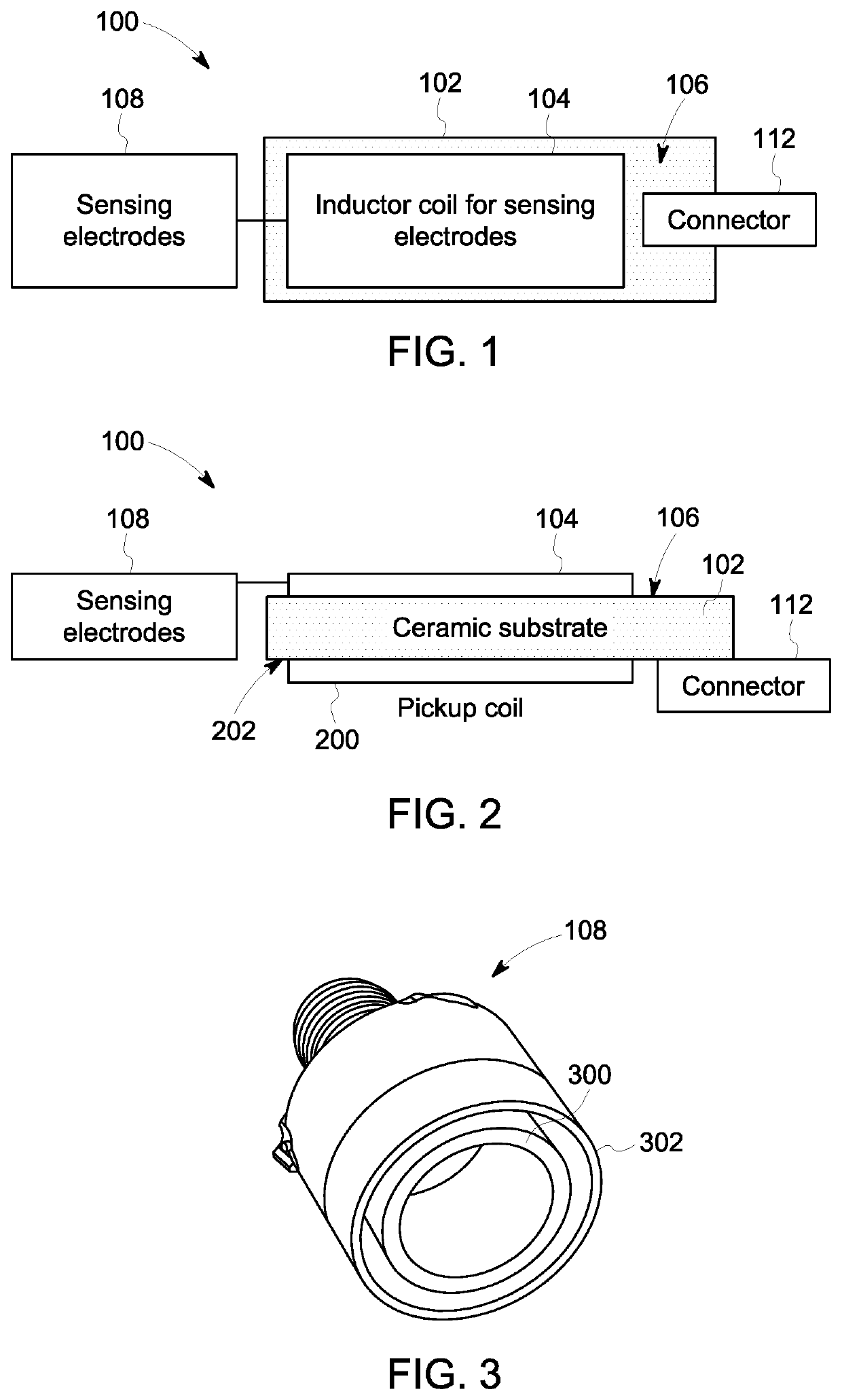
[0069]Some oil sensors are based on an inductor-capacitor-resistor (LCR) resonator structure that monitors aspects of oil operational conditions, such as levels of oil degradation and levels of external contaminants into oil. The LCR resonator operates in a multivariable mode where multiple outputs from the resonator are measured and used to detect independent changes in the oil operational conditions due to the leaks of water and fuel into the oil, and oil aging.

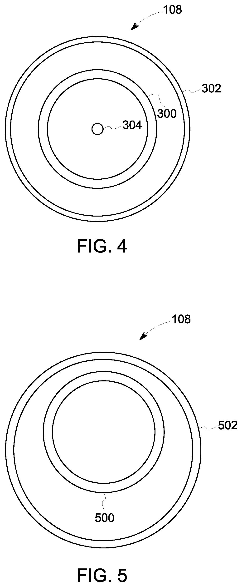
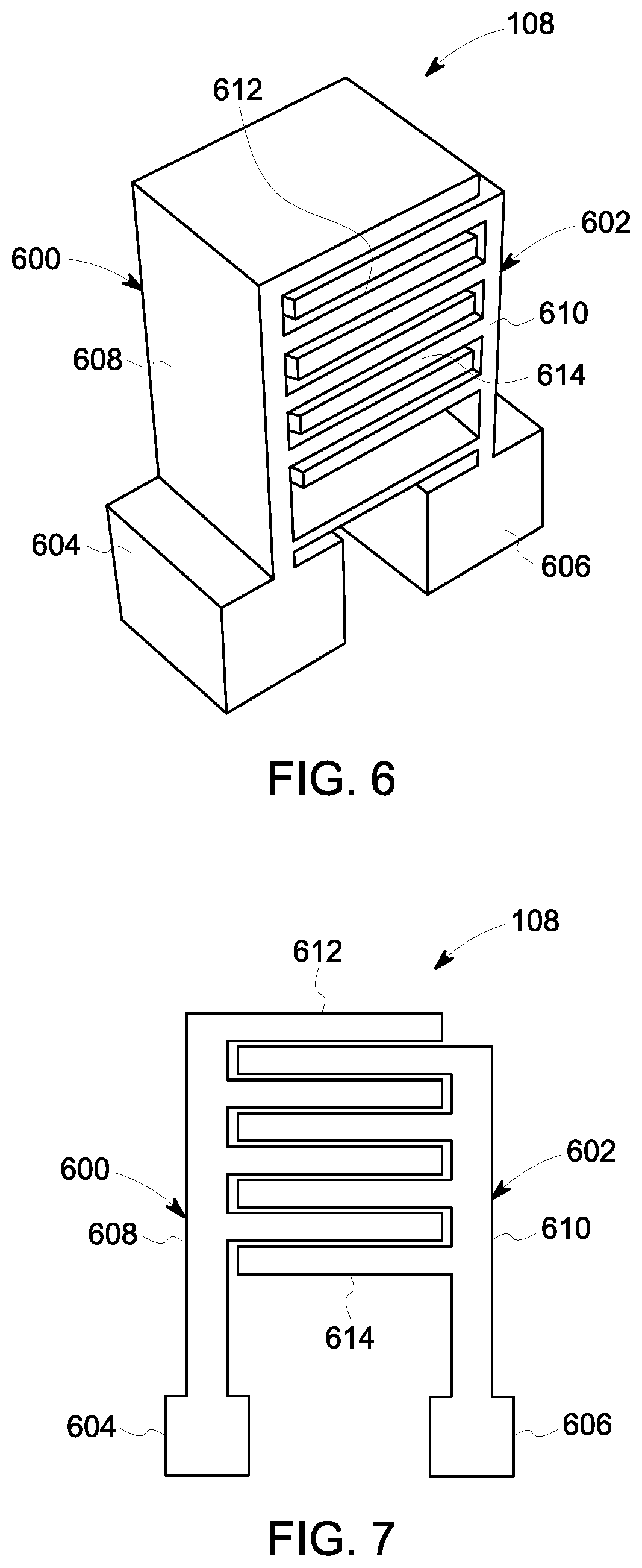
[0070]These types of sensors can involve a sensor probe comprised of two distinct components such as a sensing substrate onto which an electrode structure was deposited. The sensor probe may be a region of the sensor that is in operational contact with the measured industrial fluid (e.g., oil). Other portions of the sensor (such as sensor housing, transformer, electronics, electrical connectors, etc.) may not be in operational contact with the measured industrial fluid. The sensing substrate may be an inert material that al...


PUM

PropertyMeasurementUnit
dielectric constantsaaaaaaaaaa

Abstract

A resonant sensor probe assembly includes a substrate formed from one or more dielectric materials and free-standing electrodes coupled with the substrate. The free-standing electrodes are configured to be placed into the fluid and to generate an electric field between the free-standing electrodes. A controller measures an impedance response of the sensor to the fluid between the electrodes to determine an aging effect of the sensor.

Description

CROSS-REFERENCE TO RELATED APPLICATIONS[0001]This application is a continuation-in-part of U.S. patent application Ser. No. 17 / 224,969, filed 7 Apr. 2021, which is a continuation of U.S. patent application Ser. No. 16 / 146,322, filed 28 Sep. 2018, which claims priority to U.S. Provisional Application No. 62 / 612,855, filed 2 Jan. 2018. The entire disclosures of these applications are incorporated herein by reference.BACKGROUNDTechnical Field[0002]Embodiments of the subject matter disclosed herein generally relate to sensor probe assemblies that monitor and evaluate an operational condition of oil in various environments, such as when oil is utilized as a lubricant in engines, gearboxes, or generators, or as an electrical isolator in electrical transformers. Not all embodiments of the subject matter described herein, however, are limited to monitoring and evaluating the operational condition of oil in engines, gearboxes, or transformers.Discussion Of Art[0003]Real time monitoring and e...

Claims


Application Information

Patent Timeline
Patent Type & Authority Applications(United States)
IPC IPC(8): G01N33/28B61L3/00G01N27/22G01M15/09G01N27/02
CPCG01N33/2888B61L3/002G01N33/28G01N27/221G01M15/09G01N27/026B61L15/0081B61L15/0094
Inventor POTYRAILO, RADISLAV ALEXANDROVICHMACK, CRAIGCALVERT, CHRISTOPHERSCHERER, BRIANSCHREINER, JAMESKUZHIYIL, NAJEEB M.ADHIACHARI, SUBRAMANIKAYAL, PARTHOKARUNARATNE, MILANRODDY, NICHOLAS E.GADIYARAM, JANAKIGO, STEVENSALAZAR, VICTOR MANUEL
Owner GE GLOBAL SOURCING LLC
Learn More