Rotary type display paper money counter

A display, rotary technology used in the display of counting results, instruments, counting mechanisms/items, etc., to solve problems such as inconvenience for left-handers

Inactive Publication Date: 2008-02-20
贾哨
View PDF0 Cites 2 Cited by
  • Summary
  • Abstract
  • Description
  • Claims
  • Application Information

AI Technical Summary

Problems solved by technology

However, the display is fixedly installed on the upper cover, and can only be operated and viewed through the display facing the banknote counter. It is con

Method used


Image

  • Rotary type display paper money counter
  • Rotary type display paper money counter

Examples


Embodiment Construction

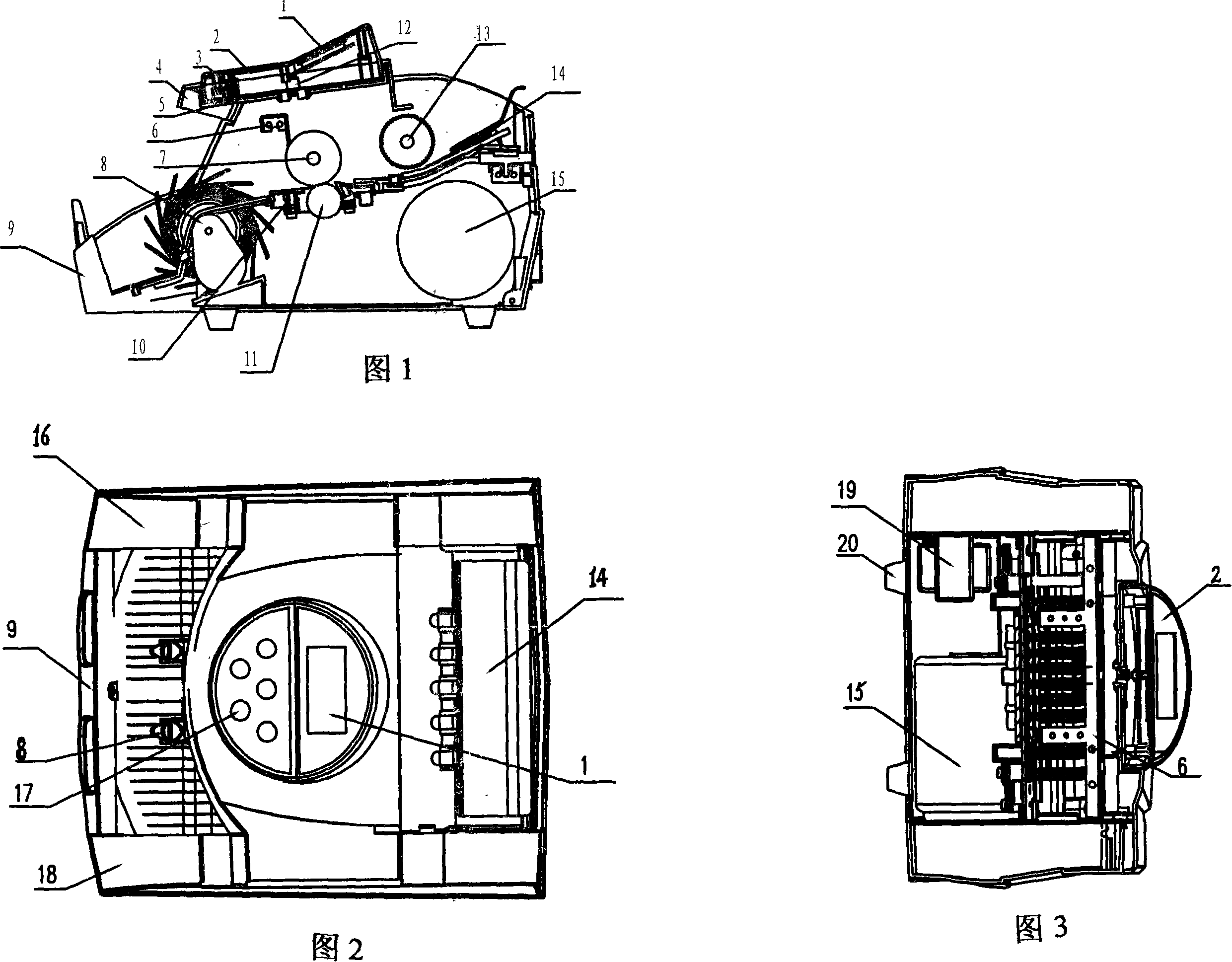
[0016] The embodiments are further described below in conjunction with the accompanying drawings.

[0017] Referring to Figure 1, Figure 2, and Figure 3, 1-display screen, 2-rotating cover, 3-slide, 4-head cover, 5-rotating fixed plate, 6-counting tube frame, 7-money output wheel, 8- Note receiving wheel, 9-note retaining plate, 10-head plate, 11-counter wheel, 12-rotating fixed shaft, 13-note feeding wheel, 14-sliding note plate, 15-transmission motor, 16-left cover, 17 -Function keys, 18-right cover, 19-transformer, 20-fixed feet. As shown in the figure, on the basis of the original banknote counter structure, the rotating display is installed on the upper part of the banknote counter as a whole, including the rotating cover 2, the head cover 4, the rotating fixed plate 5 and the rotating fixed shaft 12, and the overall rotating display is used to rotate the fixed shaft 12 is axis rotation.

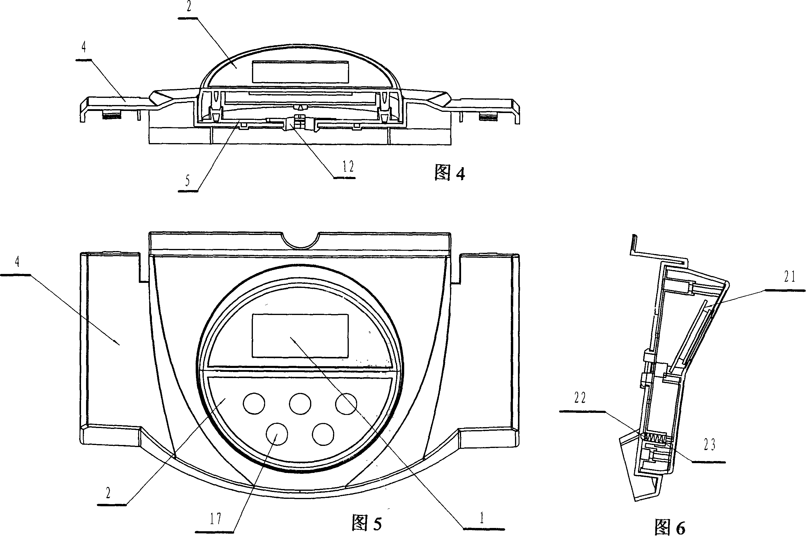
[0018] Referring to Figure 4, Figure 5, and Figure 6, 1-display screen, 2-rotatin...


PUM


Abstract

The utility model relates to a financial device, in particular to a rotary monitor type cash register, and is characterized in that a display screen and a plurality of function keys are arranged on the rotary monitor on the basis of original structure of cash register and the rotary monitor is arranged on the upper part of the cash register; the rotary monitor also comprises a rotary cover, a cap, a rotary fix plate and a rotary mounting shaft, and the whole monitor turns around the rotary mounting shaft as the axis. The rotary monitor can turn 180 degree around the axis, therefore the monitor can be operated and observed in different orientation. The utility model is more convenient than the prior device and also is suitable for the lefties.

Description

technical field [0001] The invention relates to a financial machine tool, in particular to a rotary display banknote counter capable of displaying in different orientations. Background technique [0002] The basic structure of the previous banknote counting machine includes a display screen, a counting tube frame, a banknote output wheel, a banknote receiving wheel, a banknote receiving plate, a magnetic head plate, a counter-rotating wheel, a banknote feeding wheel, a sliding banknote plate, a transmission motor, a left cover, Function keys, right cover, transformer, etc. However, the display is fixedly installed on the upper cover, and can only be operated and viewed through the display facing the banknote counter. It is convenient for people who are used to operating with the right hand, but people who are used to operating with the left hand are left-handed. Not so convenient. If the display can be operated and viewed in different directions, it will be more in line wi...

Claims


Application Information

Patent Timeline
IPC IPC(8): G06M1/00G06M3/06G06M7/06
Inventor 贾哨
Owner 贾哨
Why Eureka
Try Eureka