Plasma-generating device, plasma surgical device, use of a plasma-generating device and method of generating a plasma

a plasma-generating device and plasma-generating technology, applied in the field of plasma-generating devices, can solve the problems of large plasma-generating devices, unwieldy handling in precision work, and unwieldy plasma-generating devices in certain applications, so as to reduce the power loss of the anode, reduce the increased pressure of the plasma, and increase the effect of pressur

Active Publication Date: 2007-01-25
PLASMA SURGICAL INVESTMENTS
View PDF98 Cites 48 Cited by
  • Summary
  • Abstract
  • Description
  • Claims
  • Application Information

AI Technical Summary

Benefits of technology

[0019] The invention is based on, for instance, the knowledge that a plasma which is suitable for, for instance, cutting action in biological tissue can be obtained by designing the plasma channel in a suitable manner. An advantage of the present invention is the use of a high pressure chamber and a throttling portion which allow heating of the plasma to desirable temperatures at preferred operating currents. By pressurizing the plasma upstream of the throttling portion, it is possible to increase the energy density of the plasma in the high pressure chamber. By increased energy density is meant that the energy value of the plasma per unit volume is increased. Increased energy density of the plasma in the high pressure chamber allows, in turn, that the plasma can be given a high temperature in heating by an electric arc which extends in the same direction as the plasma channel between the cathode and the anode. The increased pressure in the high pressure chamber has also been found suitable to operate the plasma-generating device at lower operating currents. Furthermore the increased pressure of the plasma in the high pressure chamber has also been found suitable to operate the plasma-generating device at lower gas volume flows of a supplied plasma-generating gas. For example, experiments have shown that pressurization of the plasma in the high pressure chamber to about 6 bar can at least allow improved efficiency by 30% of the plasma-generating device compared with prior art technique where the plasma channel is arranged without a high pressure chamber and without a throttling portion.
[0020] It has also been found that power loss in the anode can be reduced, compared with prior art plasma-generating devices, by pressurizing the plasma in a high pressure chamber.
[0021] It may also be desirable to discharge the plasma at a lower pressure than that prevailing in the high pressure chamber. For instance the increased pressure in the high pressure chamber can be detrimental to a patient in, for example, surgical operations by a plasma-generating device according to the invention. However, it has been found that a low pressure chamber which is arranged downstream of the throttling portion reduces the increased pressure of the plasma in the high pressure chamber as the plasma passes the throttling portion when flowing from the high pressure chamber to the low pressure chamber. When passing the flow portion, parts of the increased pressure of the plasma in the high pressure chamber are converted into kinetic energy and the flow speed of the plasma is thus accelerated in the low pressure chamber in relation to the flow speed in the high pressure chamber.
[0022] A further advantage of the plasma-generating device according to the invention thus is that the plasma discharged through an outlet of the plasma channel has higher kinetic energy than the plasma in the high pressure chamber. A plasma jet with such properties has been found to make it possible to use the generated plasma for, for instance, cutting living biological tissue. The kinetic energy is suitable, for example, to allow a plasma jet to penetrate an object affected by the same and thus produce a cut.
[0023] It has also been found convenient to supply to the plasma-generating device low gas volume flows in surgical applications since high gas volume flows can be detrimental to a patient who is treated with the generated plasma. With low gas volume flows of the plasma-generating gas supplied to the plasma-generating device, it has been found that there is a risk of one or more electric arcs forming between the cathode and the high pressure chamber, referred to as cascade electric arcs.
[0024] It has also been found that the risk of occurrence of such cascade electric arcs increases with a reduced cross-section of the plasma channel. Such cascade electric arcs can have a negative effect on the function of the plasma device, and the high pressure chamber can be damaged and / or degraded owing to the effect of the electric arc. There is also a risk that substances released from the high pressure chamber can contaminate the plasma, which can be detrimental, for instance, to a patient when the plasma generated in the plasma-generating device is used for surgical applications. Experiments have shown that the above problems can arise, for instance, at a gas volume flow which is less than 1.5 l / min and a cross-section of the plasma channel which is less than 1 mm2.

Problems solved by technology

It is nowadays desirable to operate plasma-generating devices at low electric operating currents, since high electric operating currents are often difficult to provide in certain environments, such as medical environments.
As a rule, high electric operating currents also result in extensive wiring which can get unwieldy to handle in precision work, for instance in keyhole surgery.
However, a long plasma channel can make the plasma-generating device large and unwieldy to handle in certain applications, for example medical applications, especially keyhole surgical applications.

Method used


Image

  • Plasma-generating device, plasma surgical device, use of a plasma-generating device and method of generating a plasma
  • Plasma-generating device, plasma surgical device, use of a plasma-generating device and method of generating a plasma
  • Plasma-generating device, plasma surgical device, use of a plasma-generating device and method of generating a plasma

Examples


Embodiment Construction

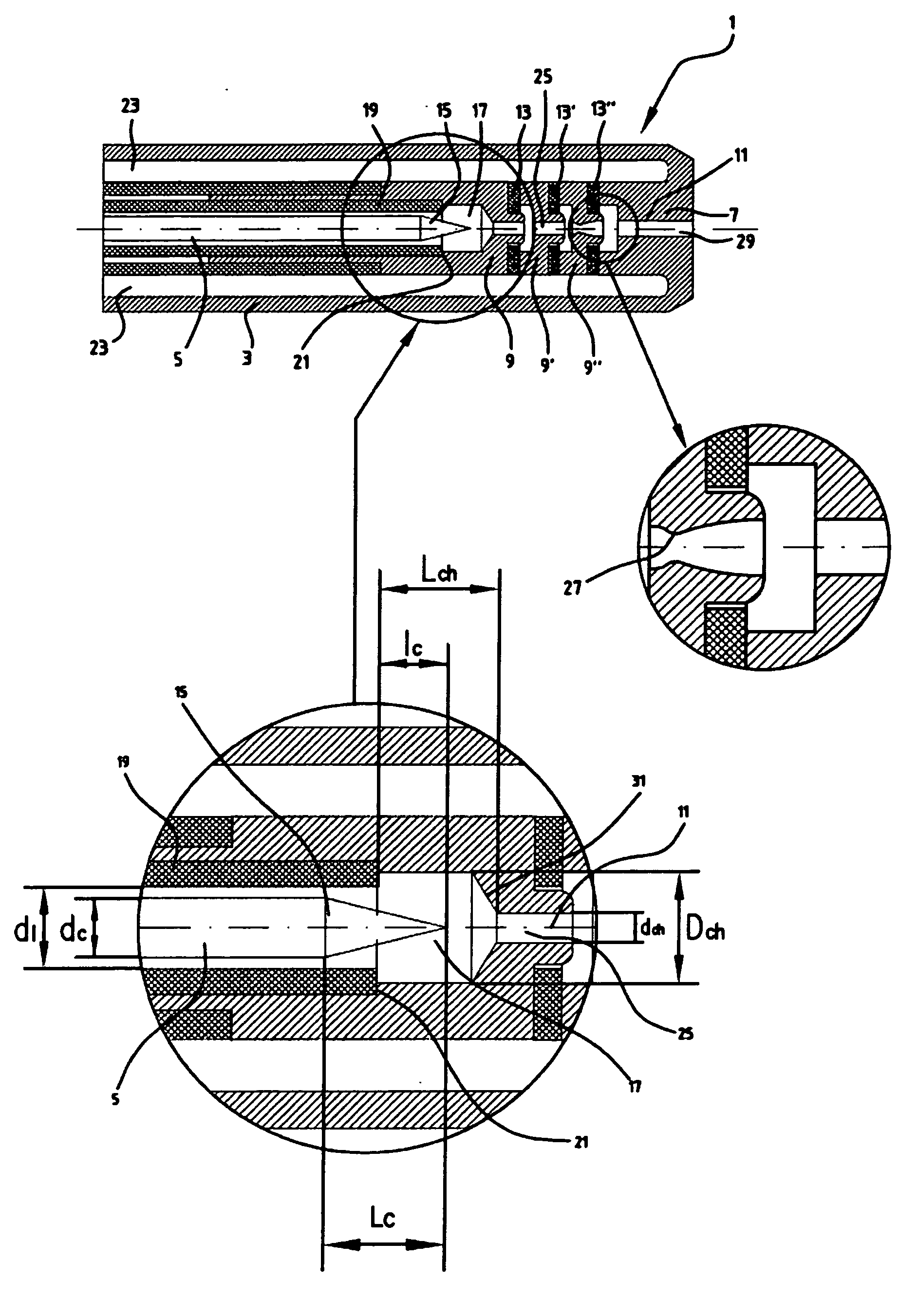
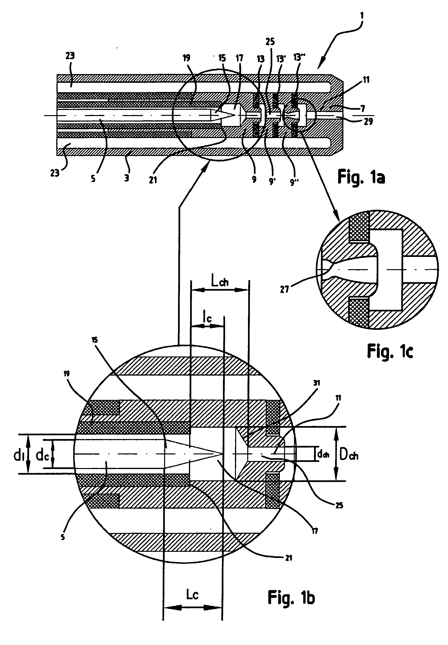
[0067]FIG. 1a is a cross-sectional view of an embodiment of a plasma-generating device 1 according to the invention. The cross-section in FIG. 1a is taken through the centre of the plasma-generating device 1 in its longitudinal direction. The device comprises an elongate end sleeve 3 which accommodates a plasma-generating system for generating plasma which is discharged at the end of the end sleeve 3. The generated plasma can be used, for instance, to stop bleeding in tissues, vaporize tissues, cut tissues etc.

[0068] The plasma-generating device 1 according to FIG. 1a comprises a cathode 5, an anode 7 and a number of electrodes 9, 9′, 9″ arranged between the anode and the cathode, in this text referred to as intermediate electrodes. The intermediate electrodes 9, 9′, 9″ are annular and form part of a plasma channel 11 which extends from a position in front of the cathode 5 and towards and through the anode 7. The inlet end of the plasma channel 11 is positioned next to the cathode ...


PUM


Abstract

The present invention relates to a plasma-generating device comprising an anode, a cathode and an elongate plasma channel which extends substantially in the direction from said cathode to said anode. The plasma channel has a throttling portion which is arranged in said plasma channel between said cathode and an outlet opening arranged in said anode. Said throttling portion divides said plasma channel into a high pressure chamber, which is positioned on a side of the throttling portion closest to the cathode, and has a first maximum cross-sectional surface transversely to the longitudinal direction of the plasma channel, and a low pressure chamber, which opens into said anode and has a second maximum cross-sectional surface transversely to the longitudinal direction of the plasma channel, said throttling portion having a third cross-sectional surface transversely to the longitudinal direction of the plasma channel which is smaller than said first maximum cross-sectional surface and said second maximum cross-sectional surface. Moreover at least one intermediate electrode is arranged between said cathode and said throttling portion. The invention also relates to a plasma surgical device, use of such a plasma surgical device in surgery and a method of generating a plasma.

Description

CLAIM OF PRIORITY [0001] This application claims priority of a Swedish Patent Application No. 0501602-7 filed on Jul. 8, 2005. FIELD OF THE INVENTION [0002] The present invention relates to a plasma-generating device, comprising an anode, a cathode and an elongate plasma channel which extends substantially in the direction from said cathode to said anode. The plasma channel has a throttling portion which is arranged in said plasma chamber between said cathode and an outlet opening arranged in said anode. The invention also relates to a plasma surgical device, use of such a plasma surgical device in surgery and a method of generating a plasma. BACKGROUND ART [0003] Plasma-generating devices relate to devices which are arranged to generate a gas plasma. Such devices can be used, for instance, in surgery to stop bleeding, that is coagulation of biological tissues. [0004] As a rule, said plasma-generating device is long and narrow. A gas plasma is suitably discharged at one end of the d...

Claims


Application Information

Patent Timeline
Patent Type & Authority Applications(United States)
IPC IPC(8): A61B18/14
CPCH05H1/24H05H2001/3484H05H2001/3452H05H1/34H05H1/3452H05H1/3484A61B18/042
Inventor SUSLOV, NIKOLAY
Owner PLASMA SURGICAL INVESTMENTS
Why Eureka
Try Eureka