Method for measuring intra-cavity loss of LD pumping solid state laser device

A solid-state laser and internal loss technology, applied in the field of lasers, can solve problems affecting laser operation and laser output, difficult to guarantee reliability, complex structure, etc., and achieve the effects of easy actual operation, no interference measurement, and simple experimental equipment

Inactive Publication Date: 2011-06-29
NANKAI UNIV
View PDF0 Cites 0 Cited by
  • Summary
  • Abstract
  • Description
  • Claims
  • Application Information

AI Technical Summary

Problems solved by technology

However, the luminescent center particles in the solid laser medium have rich energy levels and complex structures; after being excited by the pumping source, in addition to the excitation of the lower energy level particles and the radiative transition of the upper energy level particles, there are other transition processes, which occur as usual Nonradiative relaxation and upconversion luminescence in rare earth ion-doped laser media
Under the pumping conditions of LD high pumping power density, these transition processes bring additional loss, which significantly affects the operation of the laser and the laser output
Considering only the laser generation process of solid-state lasers and including the influence of other transition processes into the cavity loss, the reliability of the measurement and calculation results will be difficult to guarantee

Method used


Image

  • Method for measuring intra-cavity loss of LD pumping solid state laser device
  • Method for measuring intra-cavity loss of LD pumping solid state laser device
  • Method for measuring intra-cavity loss of LD pumping solid state laser device

Examples


Embodiment 1

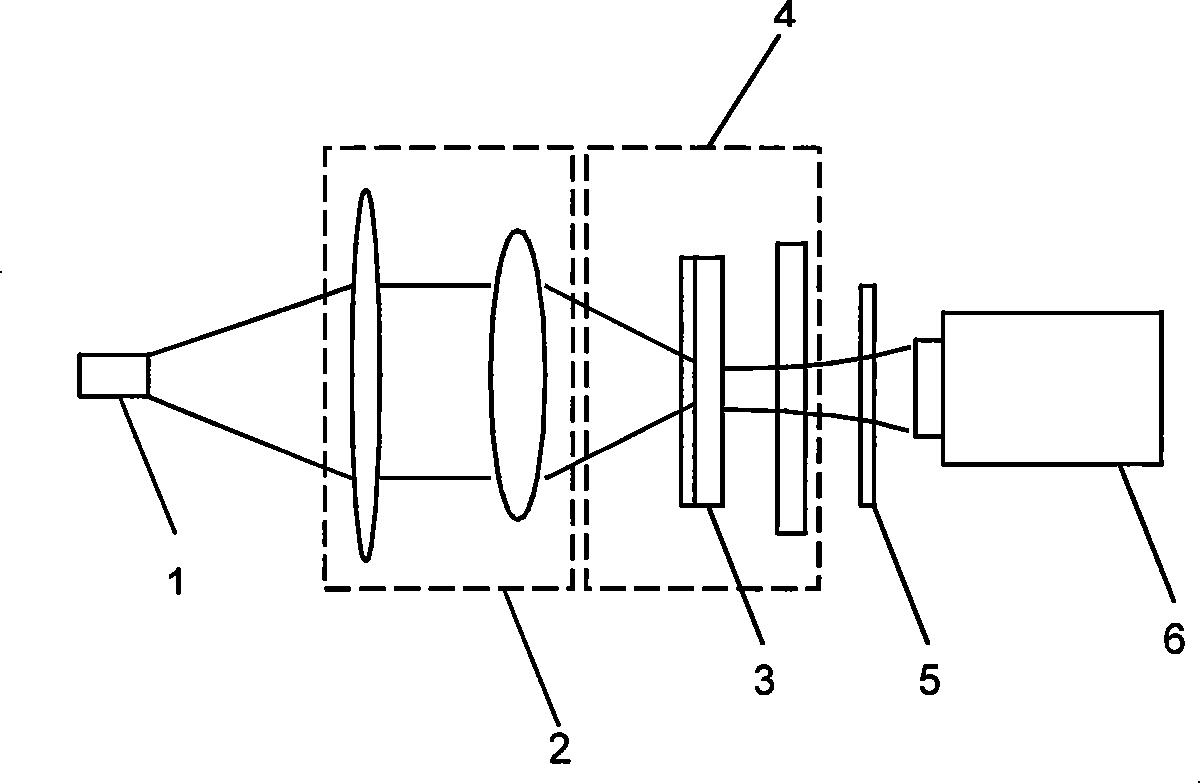
[0037] Example 1: as figure 1 As shown, the implementation device of the present invention includes a pump semiconductor laser 1 , a pump coupling system 2 , a laser medium 3 , a laser flat resonator 4 , a 975 nm filter 5 , and a power meter 6 . The pumping light with a wavelength of 975 nm output by the pumping semiconductor laser 1 passes through the pumping coupling system 2 and is coupled at the laser medium 3 into a fundamental mode Gaussian distribution circular spot with a radius of 75 μm. The laser medium 3 is an erbium-ytterbium co-doped phosphate glass microplate with a thickness of 1mm, and the erbium ion concentration is N e 9.88×10 25 / cm 3 , the ytterbium ion concentration N Y is 2.01×10 27 / cm 3. The stimulated radiation of the laser medium 3 generates light with a wavelength of 1540 nm, which is oscillated in the laser resonator 4 and output as laser light. In this example, the total reflection mirror of the microchip laser resonator is replaced by a 154...

Embodiment 2

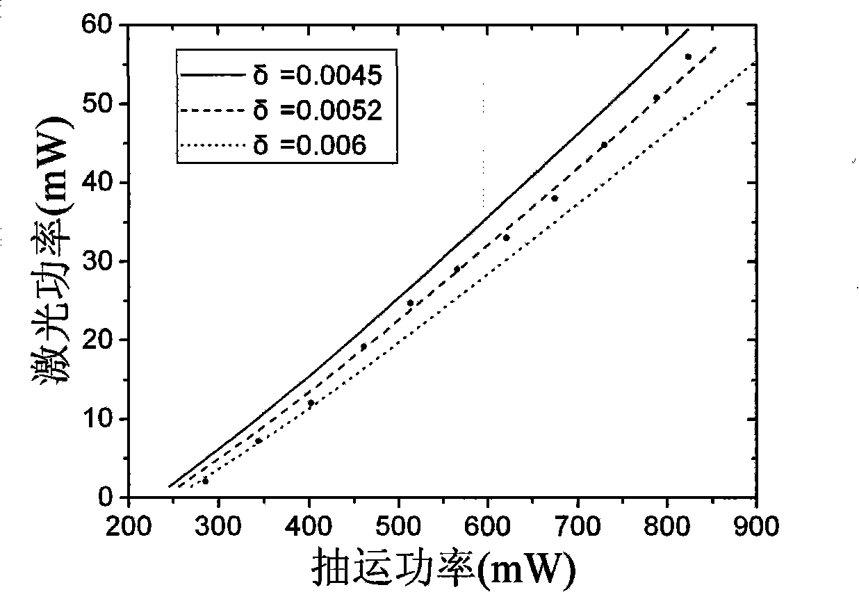
[0062] Example 2: This example is basically the same as Example 1, with the exception of Figure 4 As shown in the middle part 4, the curvature radius of the output mirror of the microchip laser resonator is 214mm, the reflectivity is 99%, and the 1540nm high-reflection film coated on the laser medium forms a plano-concave cavity. The energy level and rate equations are analyzed with Example 1 same. In the case of cavity lengths of 4.5, 5.5, and 6.5 mm, the round-trip losses in the flat-concave cavity are 0.0048, 0.0056, and 0.0059, respectively.

Embodiment 3

[0063] Example 3: as Figure 5As shown, the implementation device of the present invention includes a pumping semiconductor laser 1 , a pumping coupling system 2 , a laser medium 3 , a 975nm filter 4 , and a power meter 5 . The pumping light with a wavelength of 975 nm output by the pumping semiconductor laser 1 passes through the pumping coupling system 2 and is coupled at the laser medium 3 into a fundamental mode Gaussian distribution circular spot with a radius of 75 μm. The laser medium 3 is an erbium-ytterbium co-doped phosphate glass microplate with a thickness of 1mm, and the erbium ion concentration is N e 9.88×10 25 / cm 3 , the ytterbium ion concentration N Y is 2.01×10 27 / cm 3 . One side of the laser medium 3 close to the pump coupling system 2 is coated with a total reflection film in the 1.54μm band and an anti-reflection film with a transmittance greater than 85% in the 0.98μm band, and the other side is coated with a coating with a transmittance of 1% in ...


PUM


Abstract

A method for measuring the come-and-go loss in the cavity of an LD pumping solid laser includes the following steps: measuring the relation of the laser power and the pumping power in the experiment; then performing numerical fitting by using a rate equation and simulating the relation of the laser power and the pumping power under different cavity losses in the theory; finally obtaining a definite cavity loss value by comparing the experiment result and the theory. In the rate equation, the laser oscillation and other transition processes which affect the laser operation are considered, at the same time the pumping light and the laser are all Gaussian distribution. This invention method is particularly suitable for measuring the come-and-go loss in low gain microchip solid laser cavity.

Description

【Technical field】: [0001] The invention relates to the technical field of lasers; in particular, it relates to measuring the cavity loss of an LD pumping solid-state laser; in particular, measuring the cavity loss of an LD pumping solid-state laser when the laser cavity length is short and the gain is low. 【Background technique】: [0002] LD-pumped solid-state lasers are small in size and low in cost, and can be widely used in many fields such as laser ranging and optical communication. In the production, development and maintenance of such lasers, the round-trip loss in the cavity is an important indicator. Its relationship with the net gain of the laser is the main factor in determining the operation of the laser. In addition, accurate determination of intra-cavity round-trip loss is also a necessary condition for applying various laser techniques such as Q-switching, frequency stabilization, and mode selection to LD-pumped solid-state lasers. [0003] At present, the mo...

Claims


Application Information

Patent Timeline
Patent Type & Authority Patents(China)
IPC IPC(8): H01S3/00G01D21/00
Inventor 宋峰蔡虹刘淑静李腾田建国
Owner NANKAI UNIV
Why Eureka
Try Eureka