Filter cleaning system and method

A cleaning system and filter technology, applied to chemical instruments and methods, membrane filters, fixed filter elements, etc., can solve the problems of less effective cleaning, damage, and excessive cleaning of filters

Inactive Publication Date: 2008-03-05
BHA GROUP HLDG
View PDF0 Cites 4 Cited by
  • Summary
  • Abstract
  • Description
  • Claims
  • Application Information

AI Technical Summary

Problems solved by technology

A known disadvantage of cleaning with known reverse pulse jet cleaning systems is that the portion of the filter closest to the tube sheet experiences little or no effective cleaning
Other parts of the filter are often overwashed and can be damaged

Method used


Image

  • Filter cleaning system and method
  • Filter cleaning system and method
  • Filter cleaning system and method

Examples


specific Embodiment approach

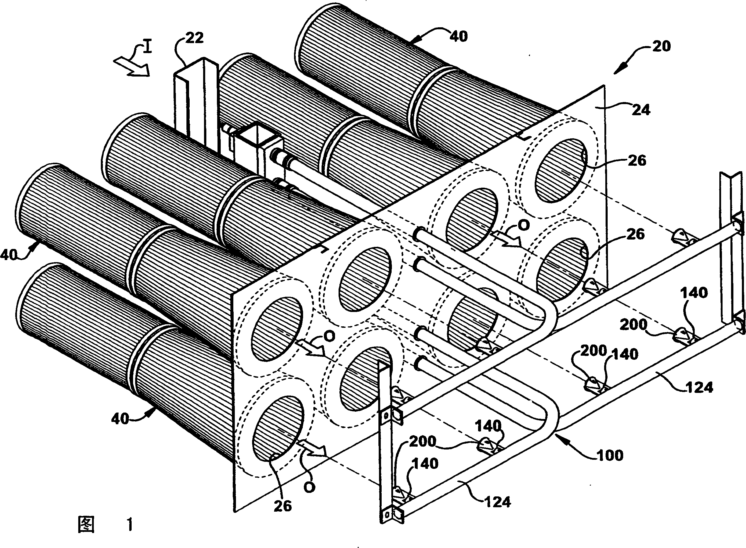
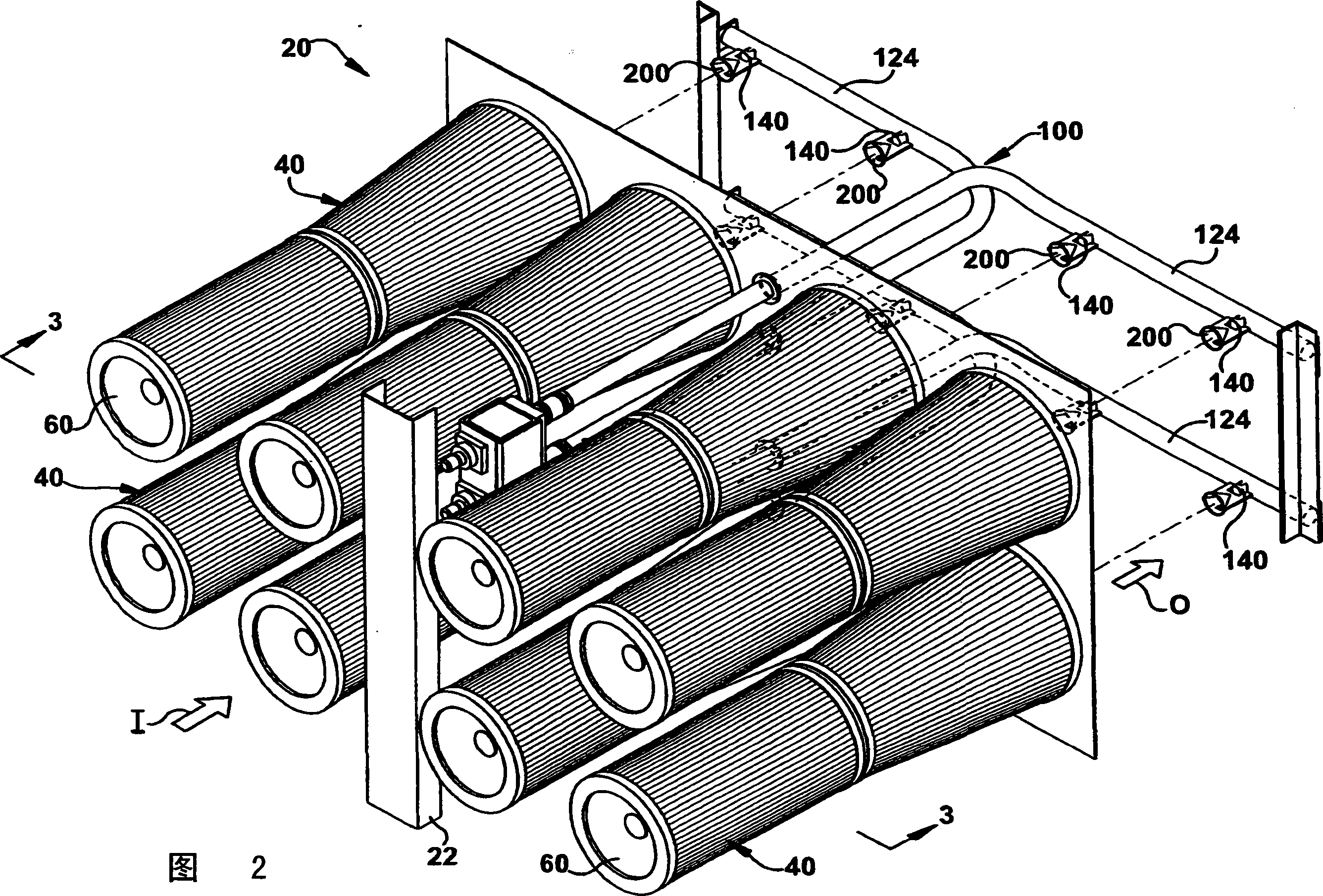
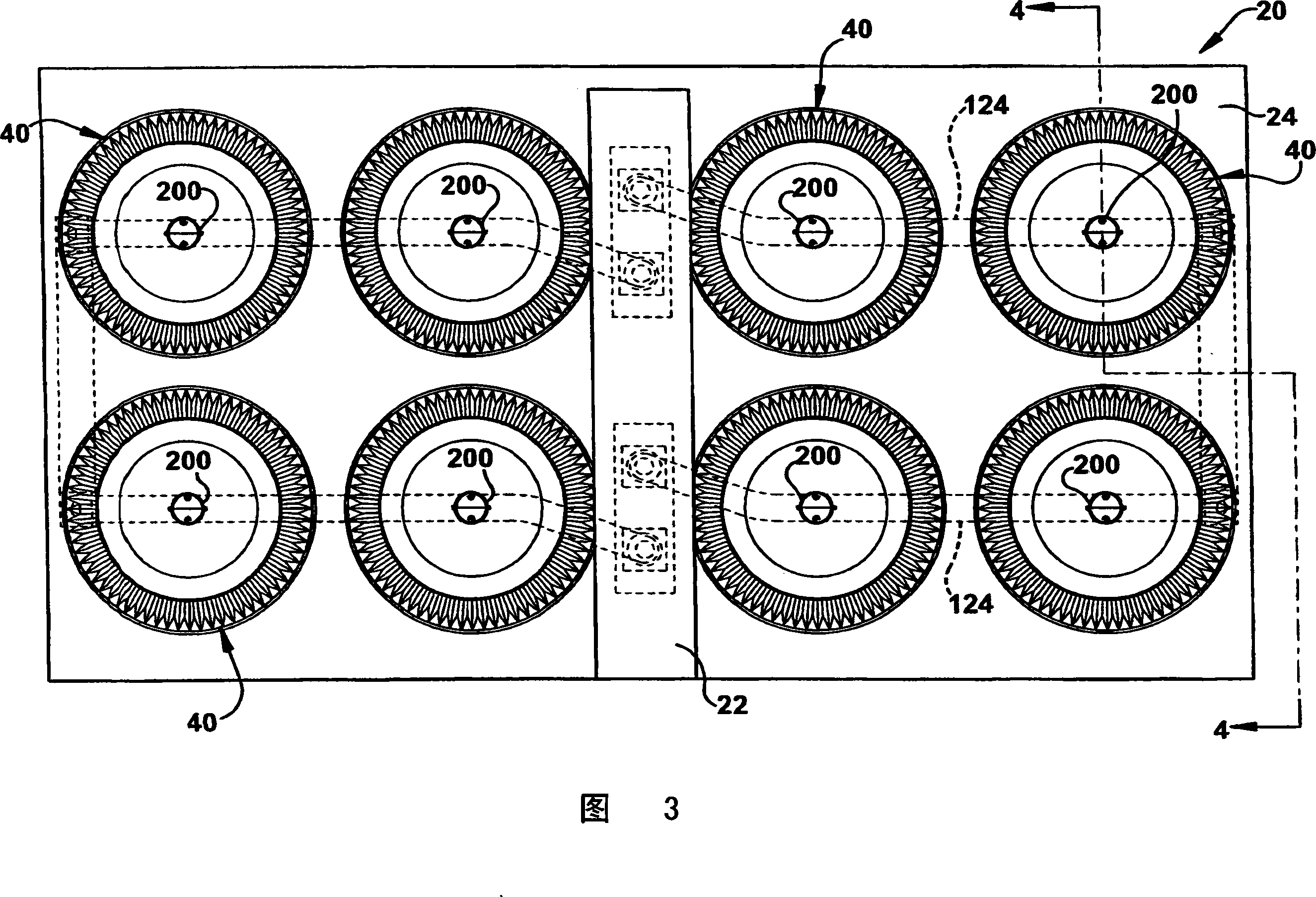
[0056] Filter system 20

[0057] Rack 22

[0058] Tube sheet 24

[0059] Opening 26

[0060] Filter assembly 40

[0061] First filter element 42

[0062] Second filter element 44

[0063] Upstream 46

[0064] Downstream side 48

[0065] (Of filter 40) proximal part 50

[0066] Filter 40) distal part 52

[0067] Removable end cap 60

[0068] Air chamber 66

[0069] Pulse jet cleaning system 100

[0070] Pulse valve 120

[0071] Manifold 122

[0072] Nozzle 124

[0073] Nozzle 140

[0074] Inlet or first end section 142

[0075] Outlet or second end section 144

[0076] Opening 160

[0077] Aspirator 180

[0078] Diffuser 200

[0079] Installation part 202

[0080] Main part 204

[0081] Exhaust notch 222

[0082] Opening 224

[0083] Diffuser (second embodiment) 300

[0084] Respective installation part 302

[0085] Installation part 302

[0086] Main part 304

[0087] Non-deflecting surface 306

[0088] Deflection surface 308

[0089] Diffuser (third embodiment) 400

[0090] Install...


PUM


Abstract

A cleaning system (100) for a gas turbine inlet filter (40) mounted to a tubesheet (24). The filter (40) defines an upstream side (46) at which particulates are separated from a fluid stream passing through the filter and a downstream side (48) substantially free of the particulates. The cleaning system (100) comprises a blowpipe (124) for supplying a pressurized fluid. A one-piece nozzle (140) is made from a tubular member having a substantially constant cross-section extending along the length of the member. The nozzle (140) is permanently attached to the blowpipe (124) at a first end portion (142). The nozzle (140) is in fluid communication with the blowpipe (124) to direct a cleaning pulse of the pressurized fluid from a second opposite end portion (144) into the downstream side (48) of the filter (40) to dislodge particulates into the upstream side. An aspirator (180) is formed in the nozzle (140) at an upstream location spaced from the second end portion (144) of the nozzle. The aspirator (180) enables an additional volume of fluid to be delivered from the second end portion (144) of the nozzle (140) than is delivered from the blowpipe (124) to the first end portion (142) of the nozzle. A diffuser (200, 300, 400) is fixed to at least one of the blowpipe (124) and the nozzle (140). The diffuser (200, 300, 400) directs a portion P1 of the cleaning pulse to a proximal portion (50) of the filter (40) located adjacent to the tubesheet (24).

Description

[0001] Cross references to related applications [0002] This application is a partial continuation of the US Patent Serial No. 11 / 493,237 filed on July 26, 2006, and the application is incorporated herein by reference. Technical field [0003] The present invention generally relates to systems and methods for cleaning filters. In particular, the present invention relates to a system and method for reverse pulse jet cleaning of a filter in a gas turbine inlet housing. Background technique [0004] It is known to use fabric filters to separate particles from flowing fluids. Over time, particles tend to accumulate on the filter media. This accumulation of particles increases the resistance to flow through the filter. Because the increased resistance prevents the fluid from passing through the filter and / or requires more power to achieve flow through the filter, it is undesirable to increase the resistance to convection. [0005] In some known systems, reverse pulse jet cleaning is u...

Claims


Application Information

Patent Timeline
Patent Type & Authority Applications(China)
IPC IPC(8): B01D29/68
CPCB01D46/0021B01D2275/201B01D46/521B01D46/0068B01D46/60B01D46/71
Inventor J·T·克莱门茨
Owner BHA GROUP HLDG
Why Eureka
Try Eureka