
Plasma film coating device and method

A technology of plasma and coating device, which is used in gaseous chemical plating, metal material coating process, coating and other directions

Active Publication Date: 2011-08-24
IND TECH RES INST
View PDF0 Cites 0 Cited by
  • Summary
  • Abstract
  • Description
  • Claims
  • Application Information

AI Technical Summary

Problems solved by technology

[0004] The method of the present invention uses the atmospheric pressure plasma production process, and cooperates with the special plasma source design, which can solve the problems faced by the traditional atmospheric pressure plasma assisted coating production process at present

Method used


Image

  • Plasma film coating device and method
  • Plasma film coating device and method
  • Plasma film coating device and method

Examples


Embodiment Construction

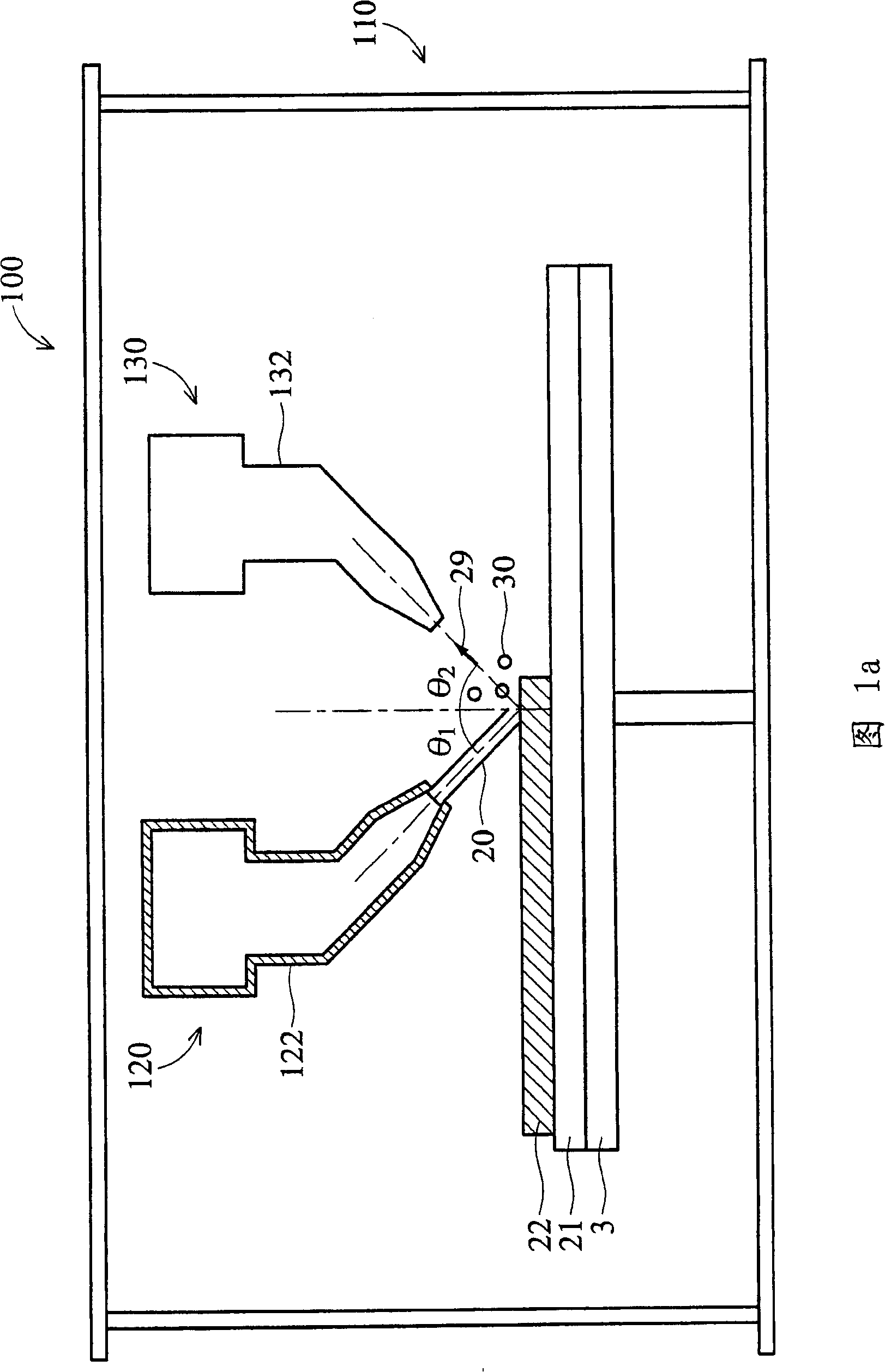
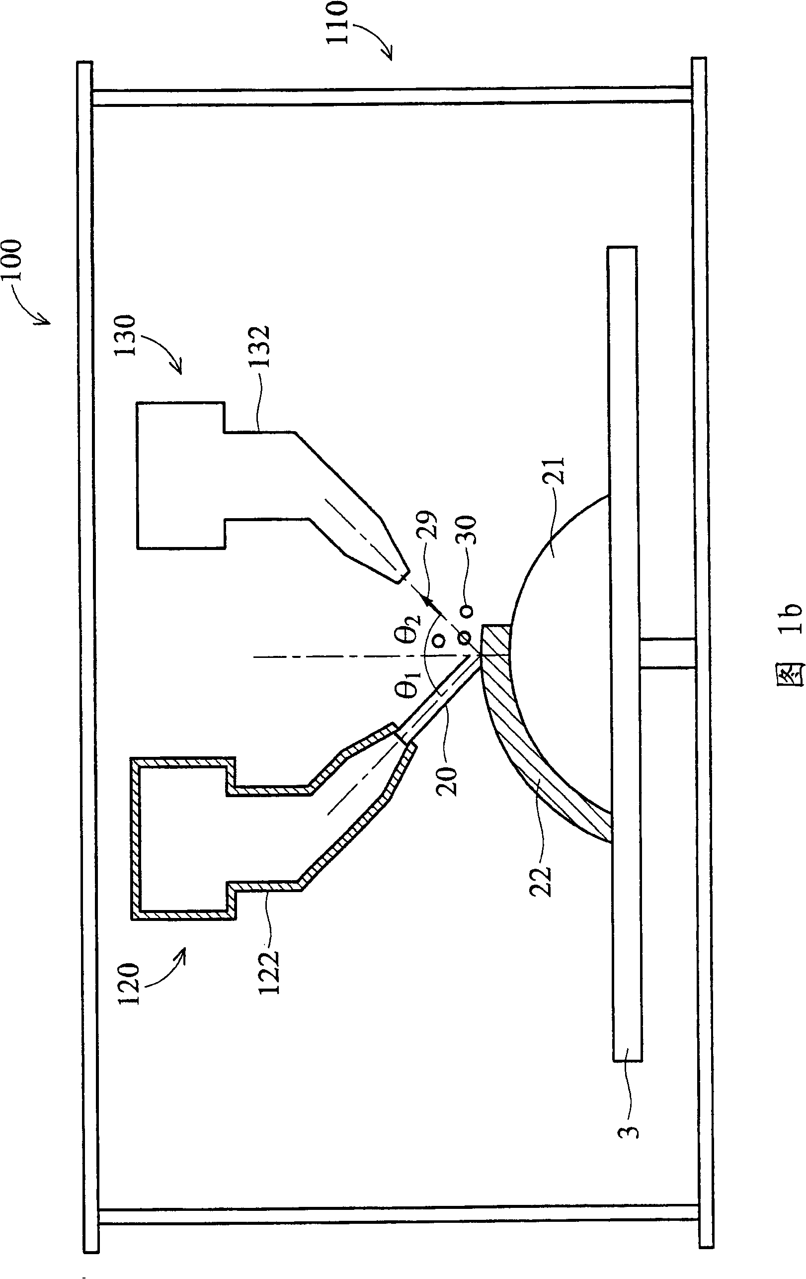
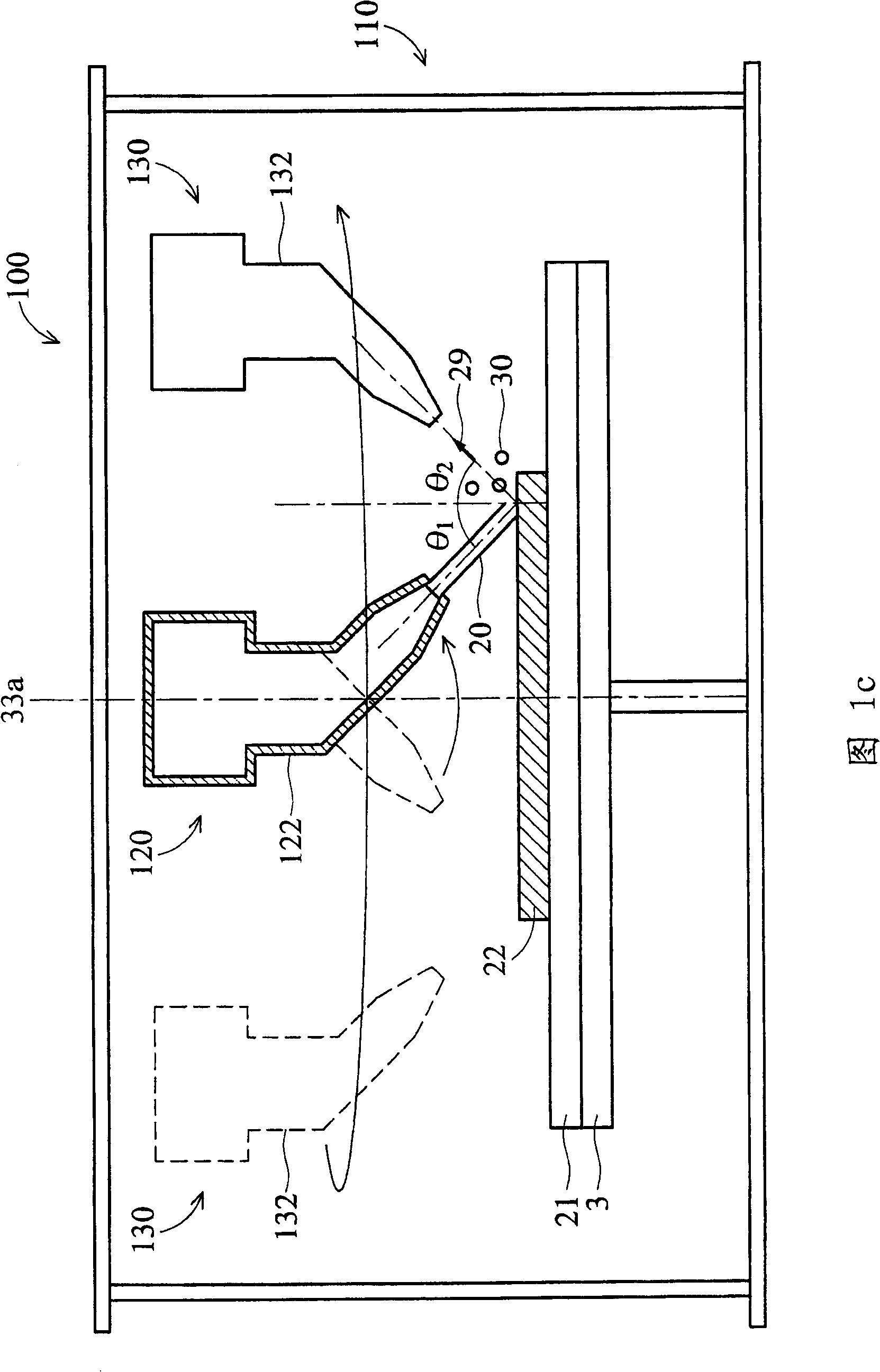
[0034] Hereinafter, the plasma coating device of the preferred embodiment of the present invention will be described in more detail by using the accompanying drawings. Figure 1a to Figure 1g The device cross-sectional views of the preferred embodiments are respectively shown, and in the various embodiments of the present invention, the same symbols represent the same components.

[0035] Please refer to Figure 1a , which shows a schematic diagram of the plasma coating device 100 in the first embodiment. The plasma coating device 100 mainly includes a reaction chamber 110 , a carrier 3 , a plasma source generating device 120 and an exhaust device 130 . The reaction chamber 110 is used to provide an environment for plasma coating. The gas pressure of the reaction chamber 110 can be normal pressure (same as external pressure, eg 760 torr) or low pressure (eg 0.1-1 torr). Furthermore, a carrier 3 is provided in the reaction chamber 110 , and the carrier 3 is used to carry the ...


PUM

PropertyMeasurementUnit
surface roughnessaaaaaaaaaa

Abstract

The invention provides a plasma coating equipment, which includes one reaction chamber; one carrier inside the reaction chamber; one plasma source generator arranged in the reaction chamber and over the carrier and including one plasma beam ejector for providing plasma beam for depositing film, the plasma beam generated by the plasma beam ejector having an included angle theta 1 more than 0 degree and less than 90 degrees with the normal line of the carrier; and one evacuating device arranged in the reaction chamber and over the carrier and including one evacuating pipe for supplying a pumping path to pump the mircoparitcle and by-product generated when the plasma beam forms the film, the included angle of the pumping pipe and the normal line of the carrier theta 2 being more than 0 degree and less than 90 degrees.

Description

technical field [0001] The present invention relates to a plasma coating device and a coating method thereof, in particular to an atmospheric pressure plasma coating device and a coating method thereof. Background technique [0002] Coating technology plays a very important role in modern industrial applications. Coating can be achieved by wet or dry methods, and advanced applications generally rely on dry manufacturing processes. Traditional dry coating technologies include physical vapor deposition (physical vapor deposition, PVD), chemical vapor deposition (chemical vapor deposition, CVD), atmospheric pressure (atmospheric pressure) chemical vapor deposition (atmospheric pressure CVD, APCVD), plasma enhanced chemical vapor deposition Vapor phase deposition (plasma-enhanced CVD, PECVD), metal organic vapor deposition (metal organic CVD, MOCVD), molecular beam epitaxy (MBE), halide vapor phase epitaxy (Halide Vapor Phase Epitaxy, HVPE), vapor deposition (Evaporation) and s...

Claims


Application Information

Patent Timeline
Patent Type & Authority Patents(China)
IPC IPC(8): C23C16/513C23C16/52
Inventor 张加强吴清吉廖新治林春宏
Owner IND TECH RES INST
Learn More