
Semi-transparent liquid crystal display device

A liquid crystal display, semi-permeable technology, applied in static indicators, instruments, nonlinear optics, etc., can solve the problem of decreased aperture ratio

Inactive Publication Date: 2008-03-05
WINTEK CORP
View PDF0 Cites 14 Cited by
  • Summary
  • Abstract
  • Description
  • Claims
  • Application Information

AI Technical Summary

Problems solved by technology

However, reserving this distance d means that a considerable electrode-free distribution area needs to be formed between the two sub-pixels, resulting in a reduction in the area actually used for display and a decrease in the aperture ratio.

Method used


Image

  • Semi-transparent liquid crystal display device
  • Semi-transparent liquid crystal display device
  • Semi-transparent liquid crystal display device

Examples


Embodiment Construction

[0021] FIG. 4 is a schematic plan view showing the design of a transflective liquid crystal display according to an embodiment of the present invention. Fig. 5 is a cross-sectional view taken along line B-B' of Fig. 4 . As shown in Figure 4, multiple parallel scan lines (scan bus lines) 12 are arranged along the horizontal direction, and multiple mutually parallel data lines (data bus lines) 14 are arranged along the vertical direction, and two adjacent scan lines 12 are orthogonal to Two adjacent data lines 14 define a surrounding area. It should be noted that what is illustrated in this embodiment is a color active matrix transflective liquid crystal display, so the surrounding area is a red (R), green (G) or blue (B) sub-pixel (sub-pixel) The distribution area of ​​the pixel electrode structure. In other words, an independently addressable display pattern element of the color active matrix transflective liquid crystal display is composed of a red, a green or a blue sub-pi...


PUM


Abstract

The LCD display thereof comprises: multi pattern components each capable of making independent addressing; each pattern component comprises a reflection area and a transmission area; the border between every two pattern components respectively belongs to the interface composed of reflection areas and transmission areas of two different pattern components. The invention can increase the viewable display area and the aperture ratio.

Description

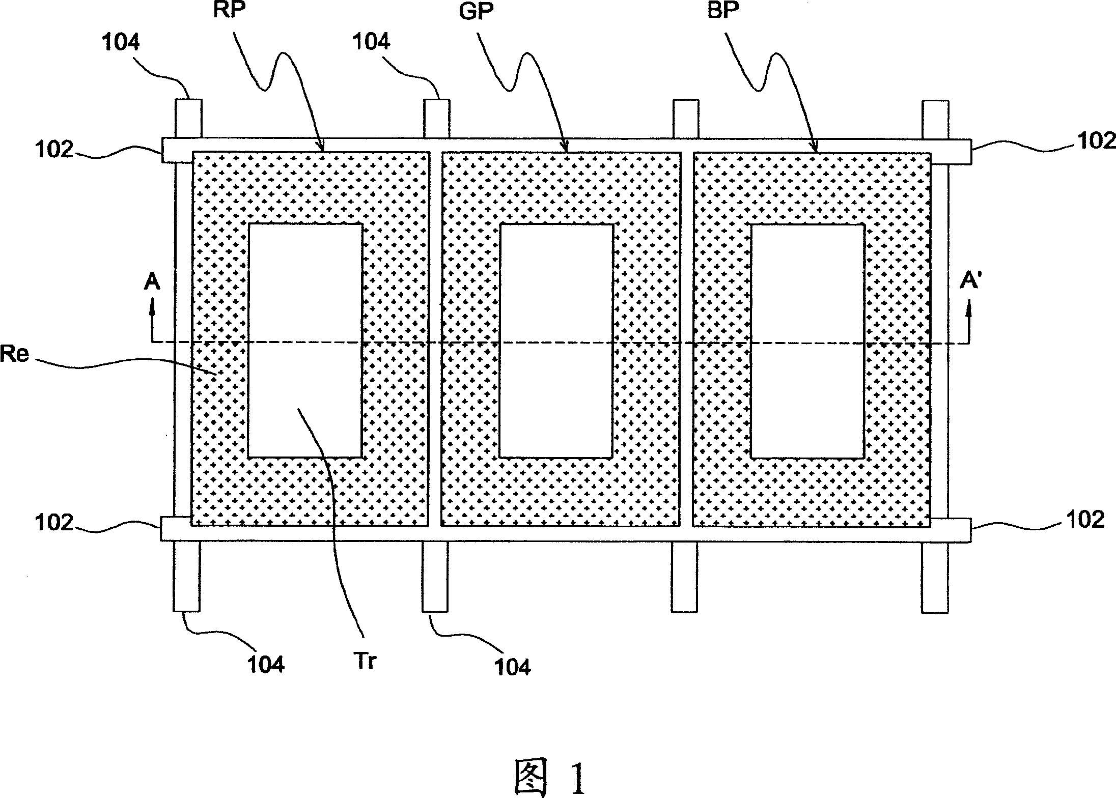
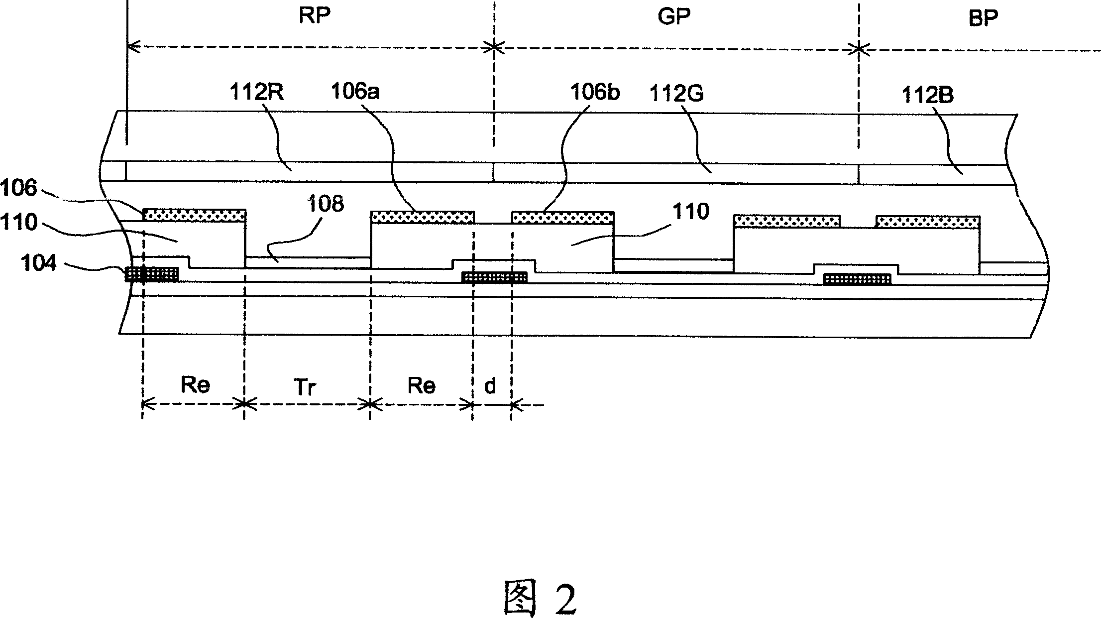
technical field [0001] The invention relates to a transflective liquid crystal display, in particular to a design of a transflective liquid crystal display with a high aperture ratio. Background technique [0002] FIG. 1 is a schematic plan view showing the design of a known transflective liquid crystal display, and FIG. 2 is a cross-sectional view obtained along line A-A' of FIG. 1 . As shown in FIG. 1 , in a transflective liquid crystal display, a plurality of parallel scan lines (scan bus lines) 102 are arranged along the horizontal direction, and a plurality of mutually parallel data lines (data bus lines) 104 are arranged along the vertical direction, and in Two adjacent scanning lines 102 are perpendicular to the area enclosed by two adjacent data lines 104, and a red sub-pixel (RP) RP, a green sub-pixel GP or a blue sub-pixel BP are distributed, Each sub-pixel includes a reflective region Re that reflects ambient light and a transmissive region Tr that allows backlig...

Claims


Application Information

Patent Timeline
IPC IPC(8): G02F1/133G02F1/1343
Inventor 郭建忠陈奕帆
Owner WINTEK CORP
Learn More