

Image stabilizer
A compensation device and a rotating shaft technology, applied in projection devices, printing devices, televisions, etc., can solve the problems of complex structure of hand shake compensation devices, inability to be mounted, and unsuitable for miniaturization.
- Summary
- Abstract
- Description
- Claims
- Application Information
AI Technical Summary
Benefits of technology
Problems solved by technology
Method used
Image

Examples
Embodiment approach 1
[0205] [1. Structure of digital camera]
[0206] First, the configuration of the digital camera of this embodiment will be described.
[0207] [1-1. Overall structure]
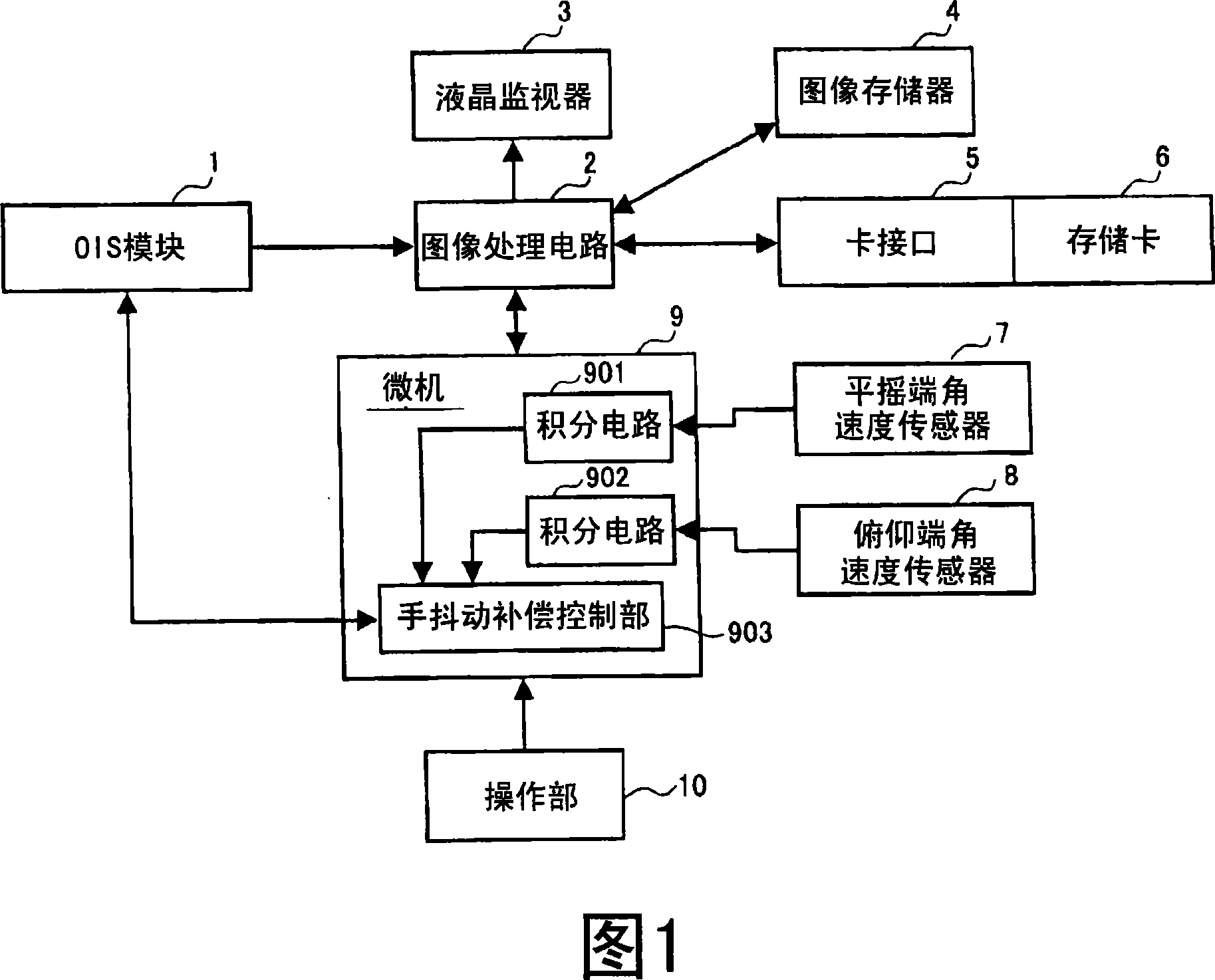
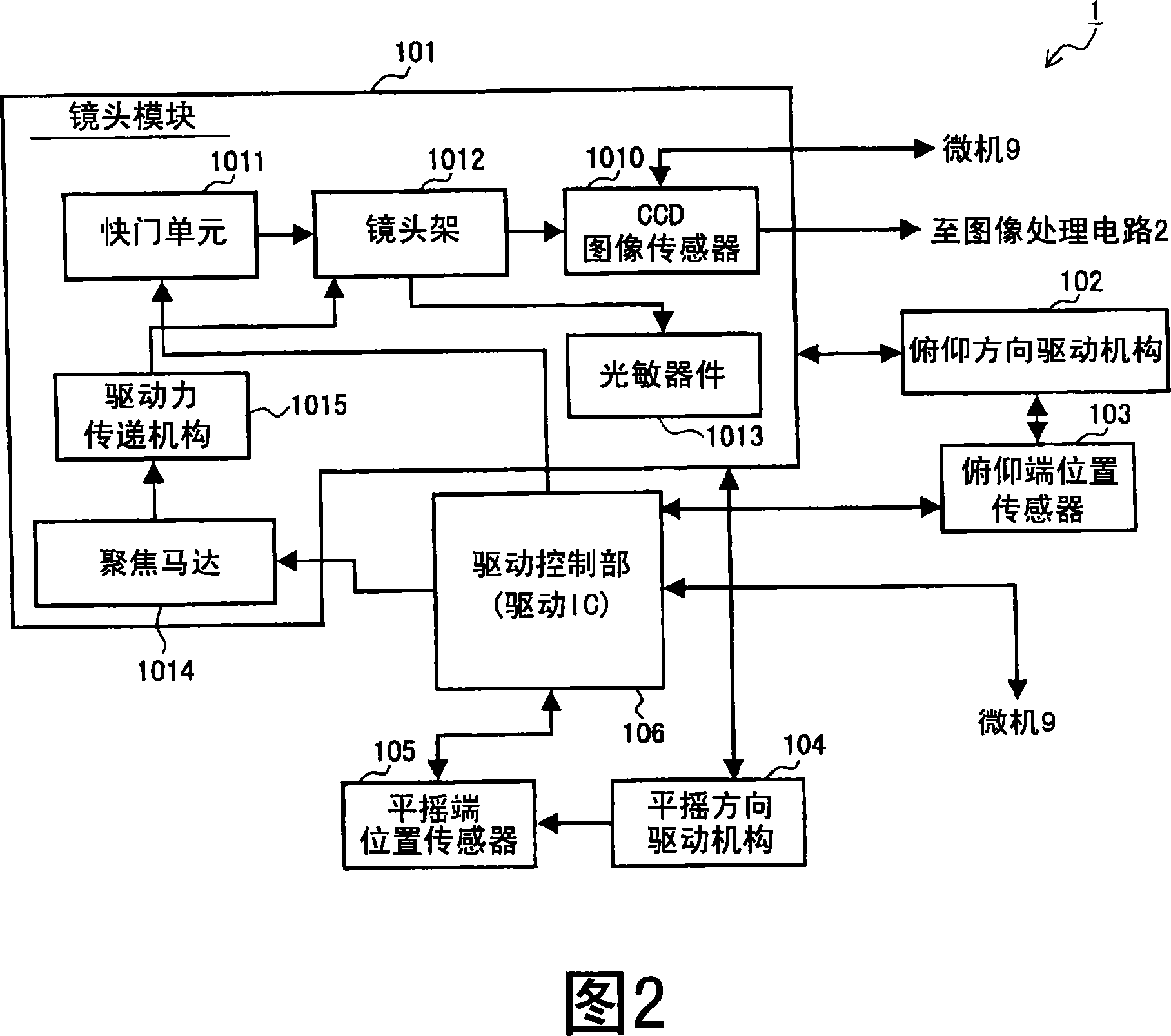
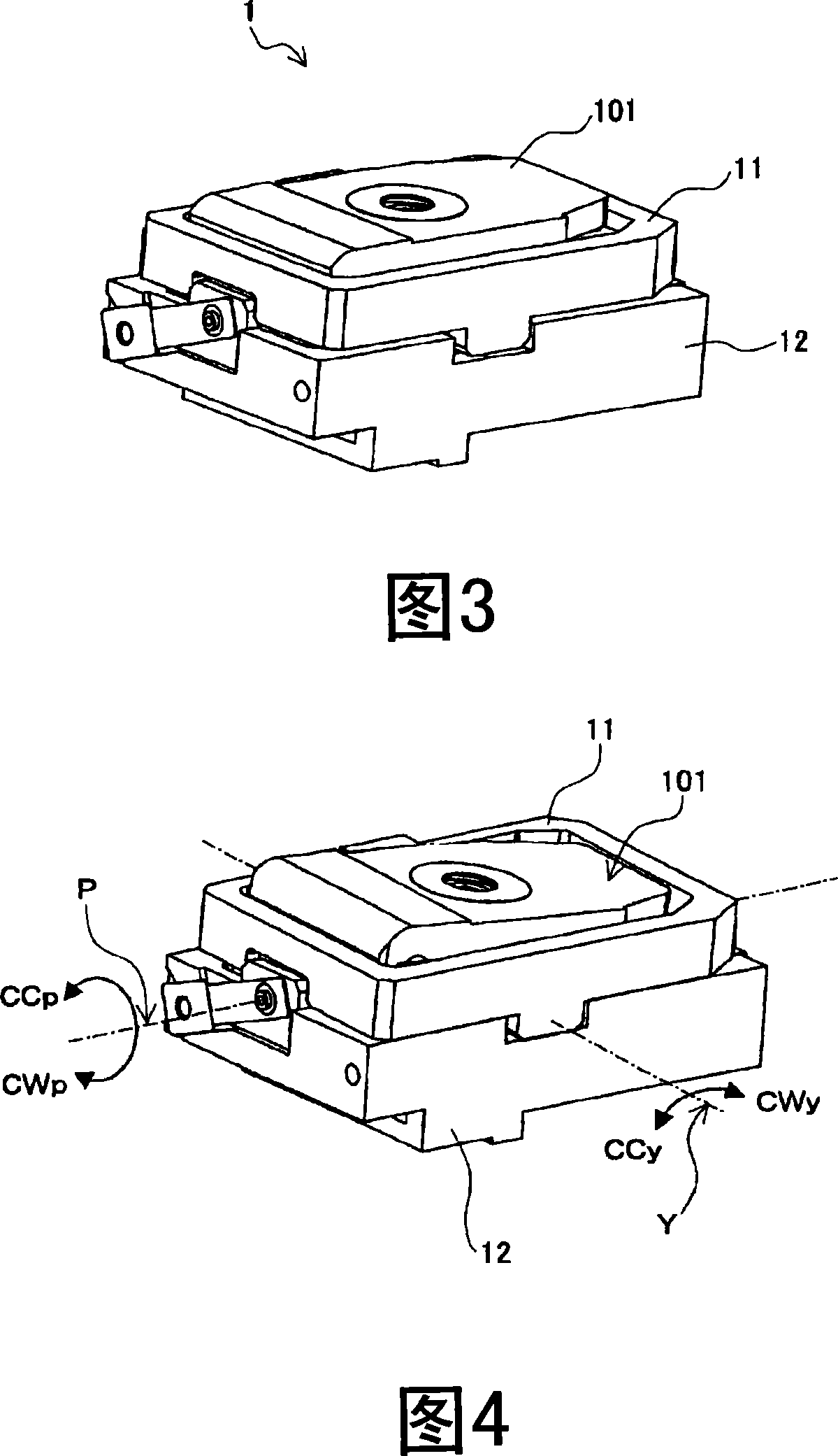
[0208] FIG. 1 is a block diagram showing the configuration of a digital camera according to this embodiment. The digital camera of this embodiment includes an OIS (optical image stabilizer: optical image stabilizer) module 1, an image processing circuit 2, a liquid crystal monitor 3, an image memory 4, a card interface 5, a memory card 6, and a pan (ヨone) terminal An angular velocity sensor 7 , a pitch end angular velocity sensor 8 , a microcomputer 9 , and an operation unit 10 .
[0209] The OIS module 1 includes a CCD image sensor (described later). The image processing circuit 2 performs image processing such as YC conversion, resolution conversion, and compression conversion on the image data generated by the CCD image sensor. The liquid crystal monitor 3 displays the image data processed by the image ...
Embodiment approach 2
[0495] Next, Embodiment 2 of the present invention will be described. However, in Embodiment 2, the same reference numerals are assigned to the same components as those in Embodiment 1 described above, and detailed description thereof will be omitted. In the following description, description will be made centering on parts different from the configuration of Embodiment 1. FIG.
[0496] [1. Control of digital camera]
[0497] [1-1. Overall action]
[0498] FIG. 49 is a block diagram showing a schematic configuration of a digital camera control system according to this embodiment. As shown in FIG. 49 , in order to perform position control around the panning axis Y, the drive control unit 106 of the OIS module 1 includes an amplitude subtraction unit 1061, an integration circuit 1071, an amplitude subtraction unit 1073, a lead filter 1063, an amplifier circuit 1065, Booster circuit 1067; in order to control the position around the pitch rotation axis P, it includes an amplitu...
Embodiment approach 3
[0560] [Connection of Piezoelectric Element and Driver (1)]
[0561] 56 is a perspective view of an assembly that drives the entire lens barrel including an imaging element such as a CCD, for explaining the connection between the piezoelectric element and the driving body according to the embodiment of the present invention. 57 and 58 are enlarged views illustrating in detail the connecting portion and constituent parts between the piezoelectric element and the driver.
[0562] In FIG. 56 , a lens barrel 3001 integrated with a lens barrel base 3001 a is adhesively fixed to a drive frame 3003 , and an imaging element 3002 such as a CCD is disposed below the lens barrel 3001 . The drive frame 3003 is rotatably supported on the rotation shaft 3014 by a fixed frame 3004 having two bearings 3003a (one of which is not shown) opposed to the optical axis 3013 at right angles. A piezoelectric element 3005 (so-called bimorph) is attached to the lower side of the fixing frame 3004 , tha...
PUM
 Abstract
Description
Claims
Application Information