Ball joint

A ball joint and ball handle technology, applied in the field of ball joints, can solve the problems of no installation, poor sealing performance of dust-proof lip, easy exposure to sewage environment, etc.

Active Publication Date: 2008-03-12
THK CO LTD
View PDF1 Cites 6 Cited by
  • Summary
  • Abstract
  • Description
  • Claims
  • Application Information

AI Technical Summary

Problems solved by technology

[0006] However, in this prior boot sealing body, any lip for forming a sealing surface is not provided as a lip sunk into the mounting groove of the ball handle body, and the lip only prevents the boot sealing body from Sliding as a purpose, the formation of the sealing surface between the boot seal body and the ball handle body only relies exclusively on the dust lip
Therefore, when the knob body swings and a pulling force acts on the dustproof lip from the side of the sealing body, the pressure on the contact surface between the front end of the dustproof lip and the knob body decreases, and the sealing performance of the dustproof lip exists. Problems that are prone to deterioration
Especially when the suspension structure of the car is easily exposed to the sewage environment, and when the ball joint is used in the part with high frequency of repeated movement of the ball handle body, the sheath sealing body is required to have extremely high sealing performance, and in the above-mentioned This requirement cannot be adequately met in existing jacket seals
[0007] In addition, since the dust-proof lip fastens the ball handle only in the radial direction, when the ball handle swings and a pulling force acts on the dust-proof lip from the side of the seal body, the dust-proof lip tends to move toward the ball handle. Axial displacement, which has also become the main reason for hindering the sealing performance of the dust-proof lip

Method used


Image

  • Ball joint
  • Ball joint

Examples


Embodiment Construction

[0017] Next, the ball joint of the present invention will be described in detail with reference to the drawings.

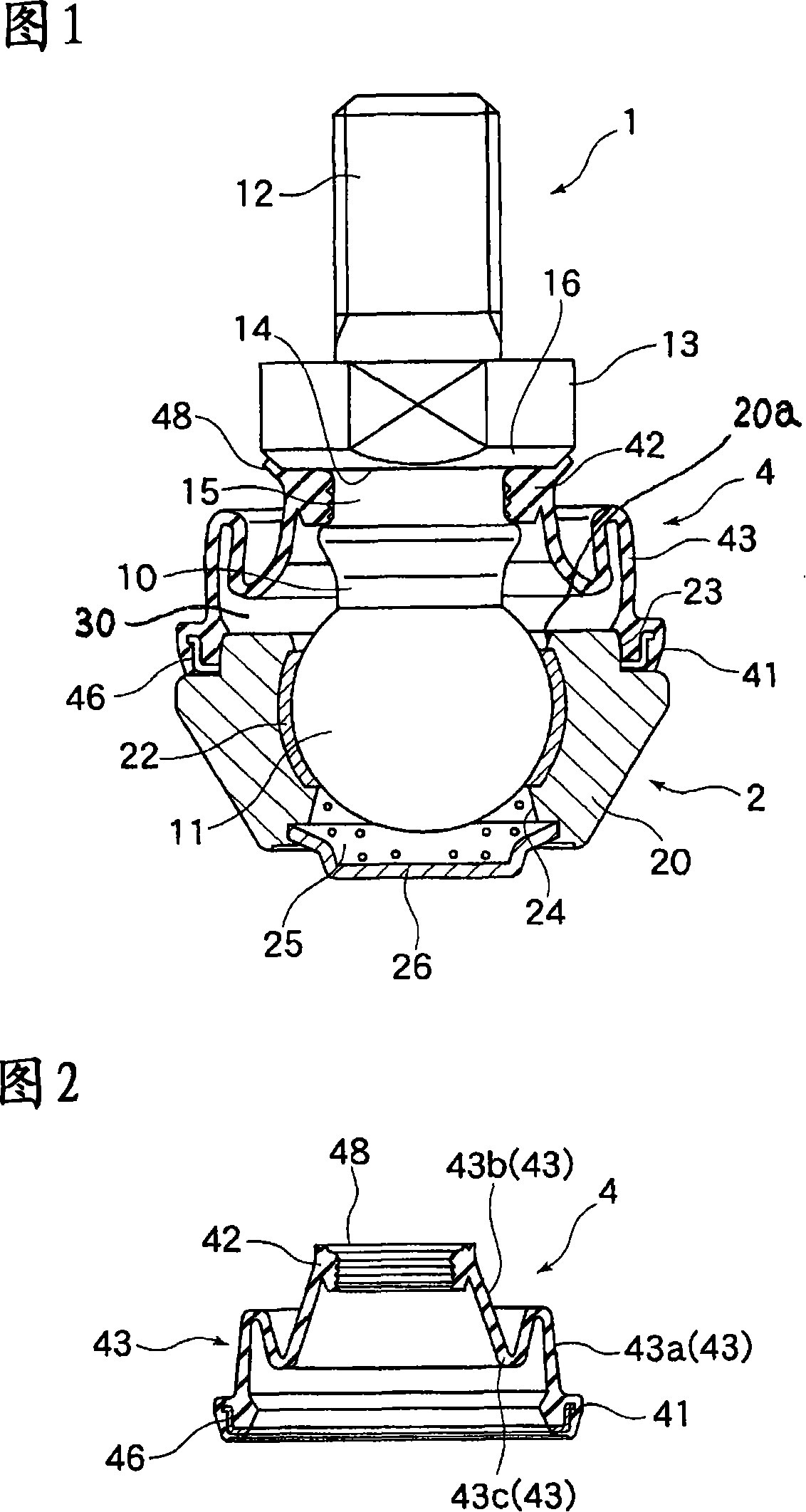
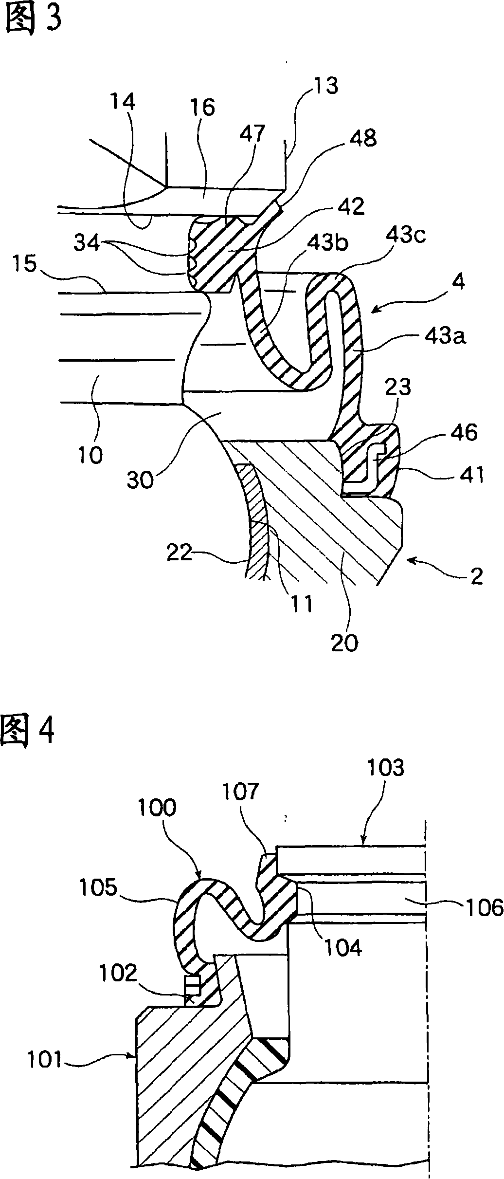
[0018] FIG. 1 is a diagram showing an embodiment of a ball joint to which the present invention is applied. In this figure, reference numeral 1 is a handle body, reference numeral 2 is a holding seat that is freely connected with the handle body 1 to swing and rotate freely, and reference numeral 4 is a handle installed to cover the handle. The sheath sealing body of the connecting part of the body 1 and the holder 2.

[0019] The knob body 1 is a member in which a ball portion 11 is formed at the tip of a substantially cylindrical shaft portion 10 . The ball portion 11 is formed by welding a high-spherical bearing steel ball to the shaft portion 10 in order to achieve smooth sliding contact with the holder 2 . In addition, a male screw portion 12 is formed at the end of the shaft portion 10 opposite to the ball portion 11, and a flange portion 13 is provided ad...


PUM


Abstract

The invention provides a ball joint, which improves the sealing performance between the sheath sealing body (4) and the ball handle body (1), and can also maintain the seal when the ball handle body (1) swings relative to the holding seat (2). performance, can completely prevent dust or sewage from invading the ball receiving portion (20) of the holder (2). A flange portion (13) is provided on the handle body (1), and a tapered surface (16) inclined relative to the axial direction of the handle body (1) is formed on the flange portion (13). The sheath sealing body (4) has an annular fixing portion fixed to the holder (2), and an annular ring that fastens the shaft portion (10) of the shank body (1) and is crimped to the flange portion (13). Shaped sealing portion (42), the side lip portion (48) corresponding to the tapered surface (16) of the flange portion (13) is protruded and formed on the sealing portion (42) in an obliquely expanded manner, and the sealing portion ( 42) When installed on the shaft portion (10) of the ball handle body (1), the side lip portion (48) is crimped on the tapered surface (16).

Description

technical field [0001] The present invention relates to a ball joint used to constitute a link mechanism, such as a suspension arm or a transmission control unit of an automobile, and more specifically, to a retainer and a retainer for preventing the intrusion of dust from the outside and engaging freely in swing and rotation Improvements between handle bodies. Background technique [0002] In the prior art, this kind of ball joint is composed of a ball handle body with a ball portion formed at the front end, and a holder formed with a ball receiving portion surrounding and holding the ball portion. The gap is in sliding contact, so that the ball handle body can freely swing within a certain angle relative to the holder, and in addition, it can also freely perform rotational movement around the axis of the ball handle body. [0003] In addition, in the ball joint constructed in this way, when dust intrudes between the ball portion of the shank body and the ball receiving po...

Claims


Application Information

Patent Timeline
Patent Type & Authority Applications(China)
IPC IPC(8): F16C11/06
CPCF16J3/042F16C11/0671F16C11/0604Y10T403/32721Y10T403/32737F16C11/0633F16C11/06F16C11/00
Inventor 白井武树荣孝司三木孝昌西出哲弘
Owner THK CO LTD
Why Eureka
Try Eureka