Apparatus on a drafting system of a spinning room machine, for weighting drafting system rollers

一种牵伸装置、设备的技术,应用在牵伸设备、纺纱机、流体压力致动装置等方向,能够解决不可能检测活塞行程等问题

Inactive Publication Date: 2008-04-16
TRUETZSCHLER GRP SE
View PDF1 Cites 9 Cited by
  • Summary
  • Abstract
  • Description
  • Claims
  • Application Information

AI Technical Summary

Problems solved by technology

Another significant disadvantage is the impossibility of detecting the stroke of the piston (up and down)

Method used


Image

  • Apparatus on a drafting system of a spinning room machine, for weighting drafting system rollers
  • Apparatus on a drafting system of a spinning room machine, for weighting drafting system rollers
  • Apparatus on a drafting system of a spinning room machine, for weighting drafting system rollers

Examples


Embodiment Construction

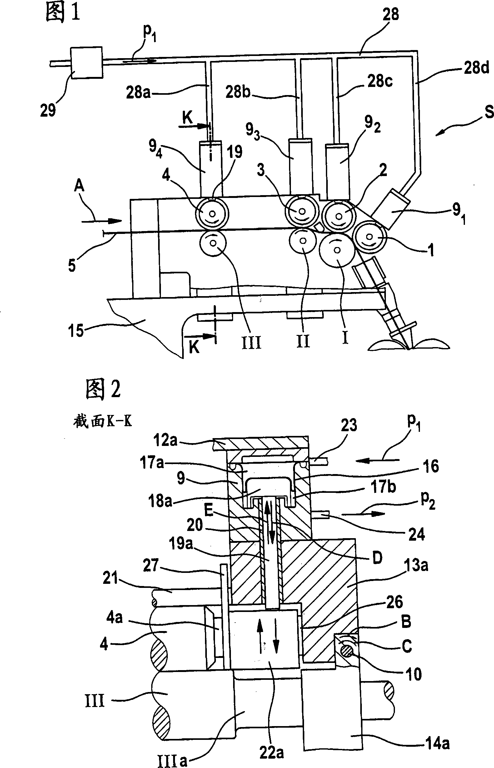
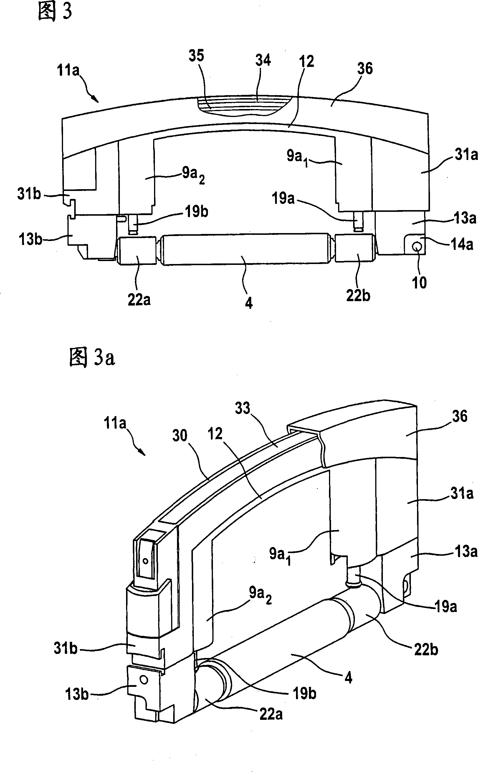
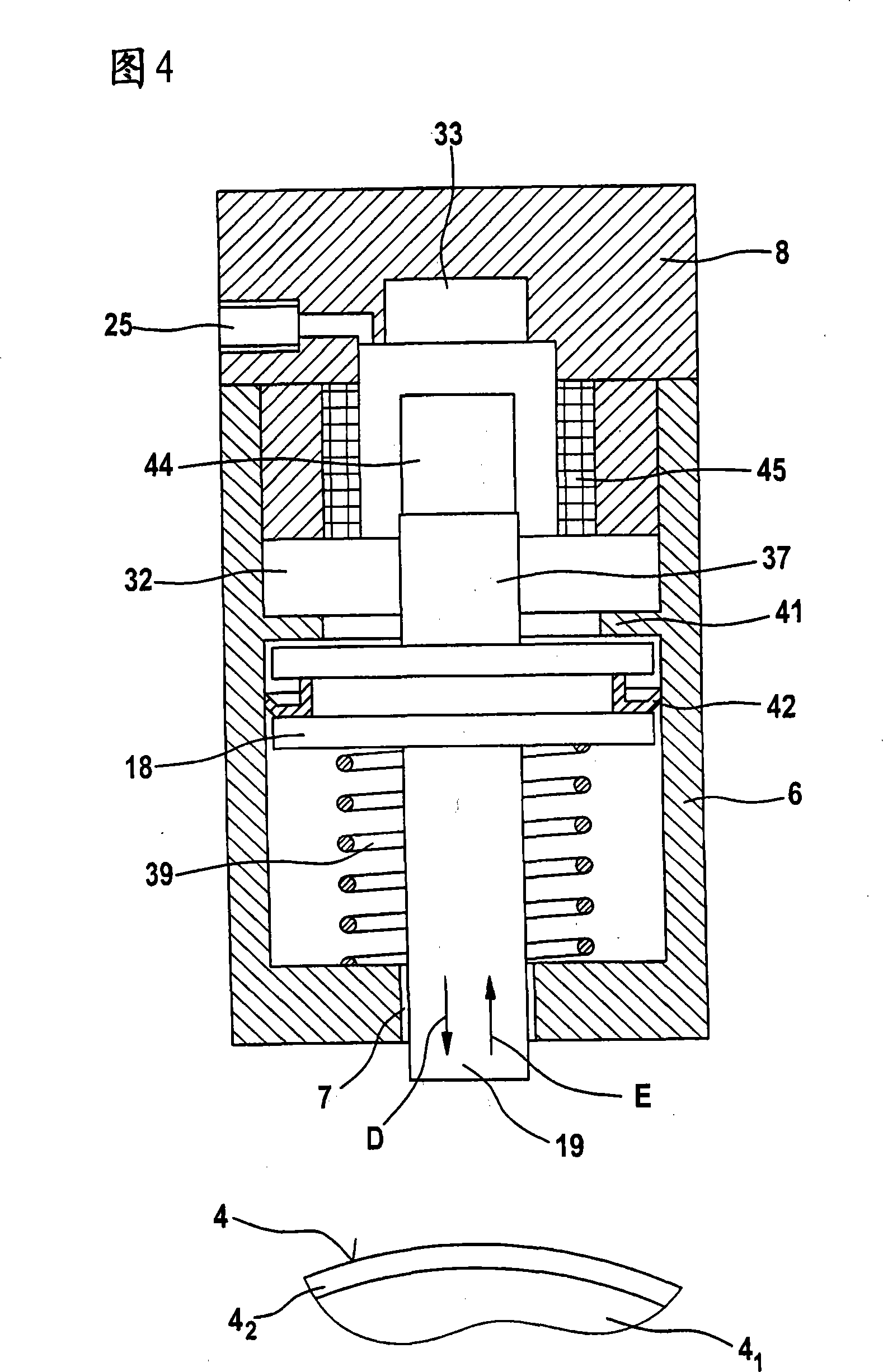
[0016] Figure 1 shows a drafting unit S such as a Trützschler Strecke TC03 draw frame. The drafting device S is constructed as a 4-up and 3-down drafting device, that is to say, it includes three lower rollers I, II, III (I draws out the lower roller, II middle lower roller, III feeds the lower roller) and Four upper rollers 1, 2, 3, 4. In the drafting device S, the drafting of the fiber bundle 5 with a plurality of slivers is performed. The drafting operation is composed of the pre-drawing operation and the main drafting operation. Roller pairs 4 / III and 3 / II form the pre-drafting zone, while roller pairs 3 / II and 1, 2 / I form the main drafting zone. The take-off lower roller I is driven by a main motor (not shown) to measure the conveying speed. Feed lower roller III and intermediate lower roller II are driven by adjustment motors (not shown). The upper rollers 1-4 pass through the pressing elements 9 in the pressing arms 11a-11d 1 ~9 4 (Loading device), pressurizing th...


PUM


Abstract

A device on a drafting device in a spinning machine, especially a drawing frame, a carding machine, a combing machine, etc., the device is used to load the drafting device roller, and it has at least one Pressure medium cylinder of a piston, the piston acts on the pressure medium and is arranged to be axially displaceable in the cylinder housing, a piston rod extends from the piston, the piston rod passes through at least one cylinder head delimiting the cylinder housing at the end, wherein , with an inductive sensor device for determining the piston position via the piston rod. In order to improve the device in order to determine the position of the piston via the piston rod, at least one inductive displacement sensor is integrated into the pressure medium system consisting of the cylinder housing and the piston which can be actuated by the pressure medium, and the inductive displacement sensor is connected with the electronic The evaluation device is connected.

Description

technical field [0001] The invention relates to a device on a drafting device in a spinning machine, especially a drawing frame, a carding machine, a combing machine, etc., the device is used for loading the drafting device roller, which has at least A pressure medium cylinder with a piston acting through the pressure medium and arranged to be axially displaceable in the cylinder housing, from which extends a piston rod which passes through at least one cylinder bounding the cylinder housing at its ends The cover, wherein an inductive sensor device is provided for determining the position of the piston via the piston rod. Background technique [0002] In a known device (EP1428914A) a switching disc is frictionally mounted coaxially with the piston so that it can move on the piston rod, the switching disc cooperating with a switch to determine the position of the piston. In order to cooperate with the inductive sensor acting as a switch to determine the piston position, the ...

Claims


Application Information

Patent Timeline
Patent Type & Authority Applications(China)
IPC IPC(8): D01H5/52D01H13/14D01H13/32H01F21/06
CPCD01H5/52D01H5/46F15B15/2815F15B15/2892D01H5/525F15B15/2861
Inventor 弗兰茨-约瑟夫·明特
Owner TRUETZSCHLER GRP SE
Why Eureka
Try Eureka