Ropeless electric connector

An electrical connector, male connector technology, applied in the direction of connection, two-part connection device, parts of the connection device, etc., can solve problems such as electric shock accidents, defects in safety performance, unsafety, etc., and achieve the effect of improving safety performance.

Inactive Publication Date: 2008-04-30
ZHEJIANG UNIV
View PDF0 Cites 11 Cited by
  • Summary
  • Abstract
  • Description
  • Claims
  • Application Information

AI Technical Summary

Problems solved by technology

The disadvantage of the above structure is that the live wire is not completely covered, and the user can see the live wire connected to the electric contact piece from overlooking the female connector, which brings unsafe feeling to the user
Although there is only a narrow slit above the contact plate of the live wire, ordinary people's fingers cannot be inserted directly, but if children insert long and thin conductive objects such as iron wires while playing, electric shock accidents will occur
Therefore, the safety performance of this structure also has defects

Method used


Image

  • Ropeless electric connector
  • Ropeless electric connector
  • Ropeless electric connector

Examples


Embodiment 1

[0035] The present invention will be further described below in conjunction with the accompanying drawings and embodiments.

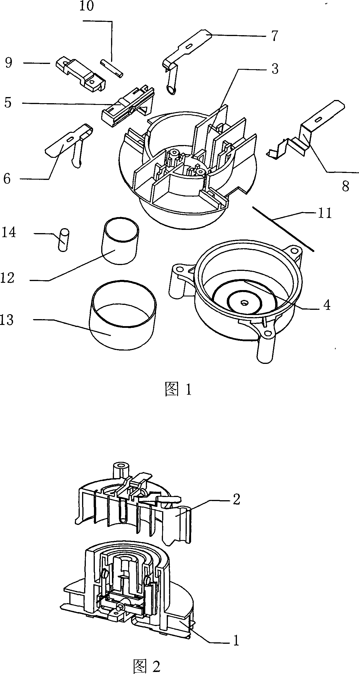
[0036] Fig. 1 is an overall exploded view of the electrical connector, which mainly includes a plastic shell and a conductive circuit. The plastic parts include base 3, cover 4, push pin 5, pin shaft 10, and fixed seat 9. The base 3 and cover 4 form the shell and provide installation positions for other parts. The push pin 5 and pin shaft 10 are transmission parts. , Fixed seat 9 is used for fixing push pin 5. Conductive components include live wire electrical contact piece 6, neutral wire electrical contact piece 7, grounding piece 8, live wire ring 12, neutral wire ring 13, grounding post 14, live wire electrical contact piece 6, neutral line electrical contact piece 7, grounding piece 8 Installed on the base 3 , the live wire ring 12 , the neutral wire ring 13 , and the grounding post 14 are installed on the cover 4 . In addition, a needle spring 1...

Embodiment 2

[0046] Embodiment 1 adopts a lever mechanism, and the offset of the electric contact piece 6 of the live line and the electric contact piece 7 of the neutral line is realized through the rotation of the lever. Embodiment 2, which is described in detail next, converts the movement of the cover 4 in the vertical direction into the movement of the push pin 5' in the horizontal direction through the inclined mechanism, and the push pin 5' further drives the electric contact piece 6 of the live line and the electric contact piece of the neutral line. 7 is offset, so that the electrical contacts 6-1, 7-1 on it press the live wire ring 12 and the neutral wire ring 13 respectively, thereby connecting the circuit.

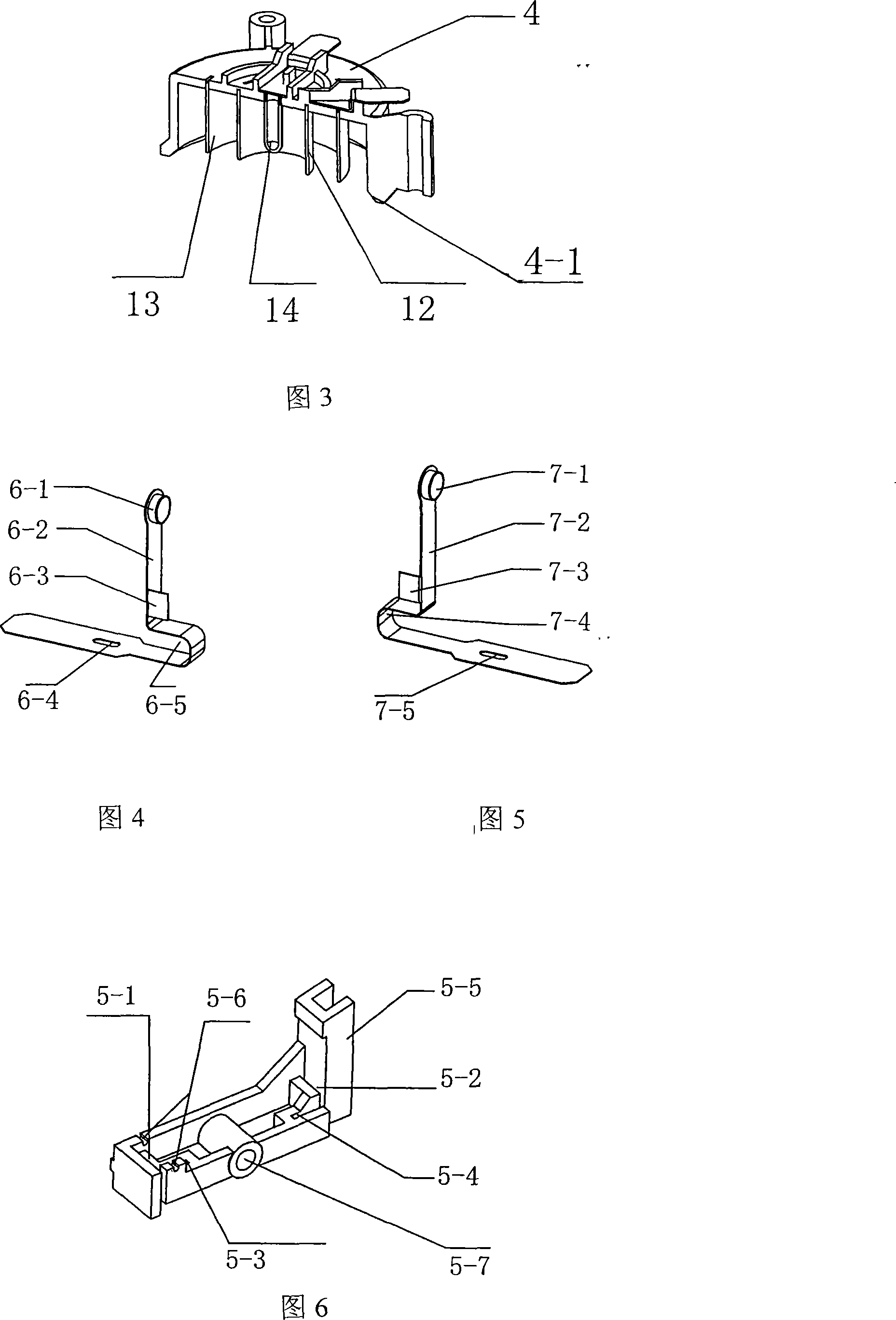
[0047] FIG. 3 is a half-section structure diagram of the male connector 2 in the electrical connector. The lower edge of the cover 4 has a circular downward pressing slope 4-1.

[0048] Fig. 13 is an oblique view of the push pin 5' in the electrical connector. Compared with...


PUM


Abstract

The invention discloses a cordless electric connector, which is nested by a positive joint and a negative joint, the positive joint is provided with a center ground stud, a power wire ring, as well as a zero wire ring, the negative joint base structure is provided with a center hole and two concentric ring grooves, the center hole is arranged with a ground lug, and the two concentric ring grooves are separately arranged with a power wire electric contact and a zero wire electric contact. The installation post of base structure lower basal surface is arranged with a push pin through a pin shaft, two ends of the push pin are respectively provided with slim grooves, two grooves are separately embedded with deflection arms on the power wire electric contact and the zero wire electric contact, a needle spring middle part is embedded in the push pin needle spring groove, two ends of the needle spring are separately inserted into two needle spring fixed grooves of the base structure, thereby making the push pin elastically position, and maintaining electric contact points of deflection points of the power wire electric contact and the zero wire electric contact in the groove-shaped matte cavity of the base structure. Because the negative joint is increased with the push pin mechanism, when the push pin is operated to the preset position, the electric contacts are in the covered positions, thereby improving safety performance for electric connectors.

Description

technical field [0001] The invention relates to an electrical connector, in particular to a cordless electrical connector. technical background [0002] The electrical connectors of existing household appliances are constantly improving in terms of safety. In terms of cordless electrical connection, the patent GB2318926A discloses a cordless electrical connector and its joint, which provides a male joint and a female joint matched therewith. The male connector includes a cylindrical first connecting terminal and a second connecting terminal annularly arranged around the first connecting terminal, and the female connector includes electric contact pieces respectively engaged with the first and second connecting terminals. The disadvantage of the above structure is that the live wire is not completely covered, and the user can see the live wire contacting the electric contact piece from overlooking the female connector, which brings unsafe feeling to the user. Although there...

Claims


Application Information

Patent Timeline
Patent Type & Authority Applications(China)
IPC IPC(8): H01R13/44H01R13/71H01R13/703H01R24/02H01R24/38
Inventor 曾令斌潘双夏冯培恩
Owner ZHEJIANG UNIV
Why Eureka
Try Eureka