Distributed timing system

A timing system, distributed technology, applied in time division multiplexing system, data exchange through path configuration, electrical components, etc., can solve the problems of high system cost, complicated wiring, difficult maintenance, etc., to simplify wiring , The effect of reducing the connection failure rate and facilitating maintenance

Inactive Publication Date: 2012-05-23
INST OF PLASMA PHYSICS CHINESE ACAD OF SCI
View PDF0 Cites 2 Cited by
  • Summary
  • Abstract
  • Description
  • Claims
  • Application Information

AI Technical Summary

Problems solved by technology

When this centralized timing system is used in the above-mentioned distributed system, many optical fibers need to be connected between each subsystem and the timing system. If several channels of signals are needed, corresponding channels must be connected between the timing system and the subsystems. Optical fiber, resulting in complicated connection between each subsystem and the timing system, high failure rate, difficult maintenance, and high system cost

Method used


Image

  • Distributed timing system
  • Distributed timing system
  • Distributed timing system

Examples


Embodiment Construction

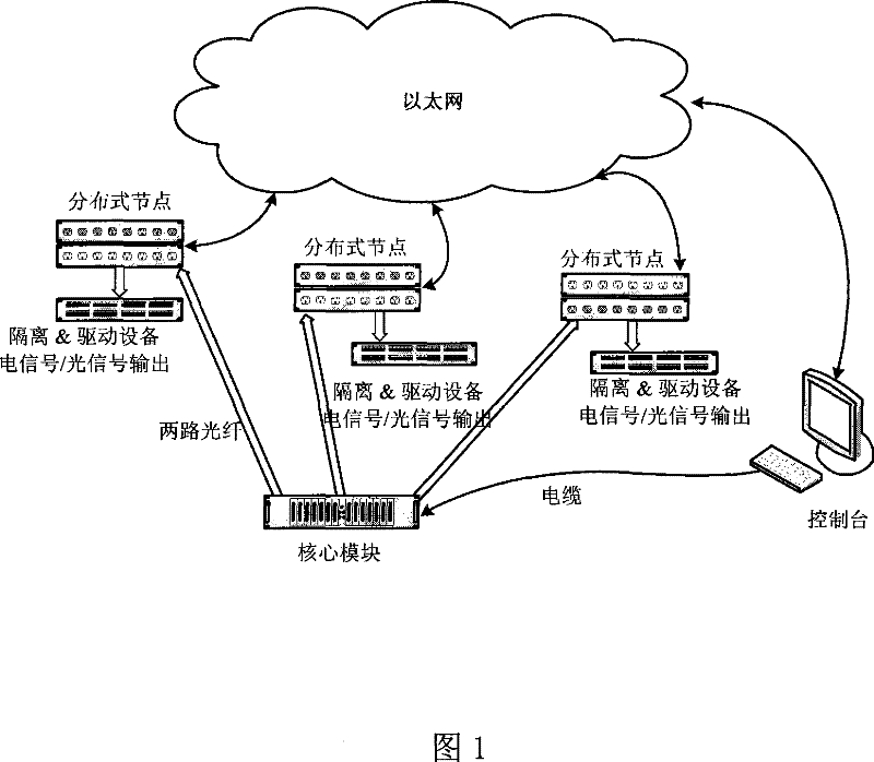
[0025] see figure 1 , the system consists of a console, core modules, distributed nodes, peripheral isolation drive equipment, and interwoven optical fiber signal network and Ethernet to form a control network and a tree signal network;

[0026] For the setting of the optical fiber signal network, due to the different physical locations of each distributed node, in order to prevent the signals between the nodes from forming a common "ground" loop, each node is connected to the core module by optical fiber. In the specific implementation, there are two optical fiber connections between the core module and each distributed node, one is the system clock signal transmission optical fiber, and the other is the system pulse trigger signal transmission optical fiber; in order to ensure that the system clock and system trigger of each distributed node The signals are all synchronous, and the length of the optical cable connecting the core module to each distributed node is set to be c...


PUM


Abstract

A distributed type timing system is provided, which is characterized in that a tree-shaped signal network is set and the distributed nodes are correspondingly set according to different physical locations of distributed subsystems. A core module provides for each distributed subsystem a plurality of synchronous square wave system clocks and synchronous system pulse trigger signals through the distributed nodes. A local operation network is set; each distribution type node and a console are together connected into the Ethernet. One route of the console provides the core module with system trigger pulse electric signal through a cable; the other route sets each clock on each distributed node and an output channel through the Ethernet to realize the transmission of the control command and the parameter. The invention provides accurately synchronous square wave clock signals and accurate pulse trigger time sequence for large devices which have a distributed system structure with simple and reliable system setting.

Description

technical field [0001] The present invention relates to a timing system, and more particularly provides a timing system for controlling timing for a large-scale device including several subsystems and adopting a distributed system structure. Background technique [0002] In large installations, timing systems are used to provide control timing for the installation. For example, in a large-scale tokamak nuclear fusion experimental device that includes many subsystems, the master console controls the operation timing of each subsystem through a timing system to ensure the coordinated operation of each subsystem of the device. With the development of thermonuclear fusion research, large-scale nuclear fusion experimental devices such as EAST full superconducting tokamak adopt a distributed system structure, and each subsystem is distributed in different physical locations, independent of each other and interacting with each other. . [0003] As ...

Claims


Application Information

Patent Timeline
Patent Type & Authority Patents(China)
IPC IPC(8): H04J3/06H04L12/28
Inventor 季振山吴一纯罗家融
Owner INST OF PLASMA PHYSICS CHINESE ACAD OF SCI
Why Eureka
Try Eureka