Birotor beater disintegrating machine

A hammer-type pulverizer and double-rotor technology, which is applied in the direction of grain processing, etc., can solve the problems that the relative linear velocity between the hammer and the material cannot be increased, and the pulverization efficiency of the pulverizer is limited, so as to increase the high-efficiency striking area, improve the pulverization efficiency, Improve the effect of striking effect

Inactive Publication Date: 2010-07-14
TIANMEN JINJIANG FOOD MACHINERY
View PDF8 Cites 2 Cited by
  • Summary
  • Abstract
  • Description
  • Claims
  • Application Information

AI Technical Summary

Problems solved by technology

However, this double-rotor pulverizer cannot increase the relative linear velocity between the hammer and the material, so the improvement of the pulverization efficiency of this pulverizer is very limited.

Method used


Image

  • Birotor beater disintegrating machine
  • Birotor beater disintegrating machine
  • Birotor beater disintegrating machine

Examples


Embodiment Construction

[0014] The structure of the present invention will be described in detail below in conjunction with the accompanying drawings.

illustration:

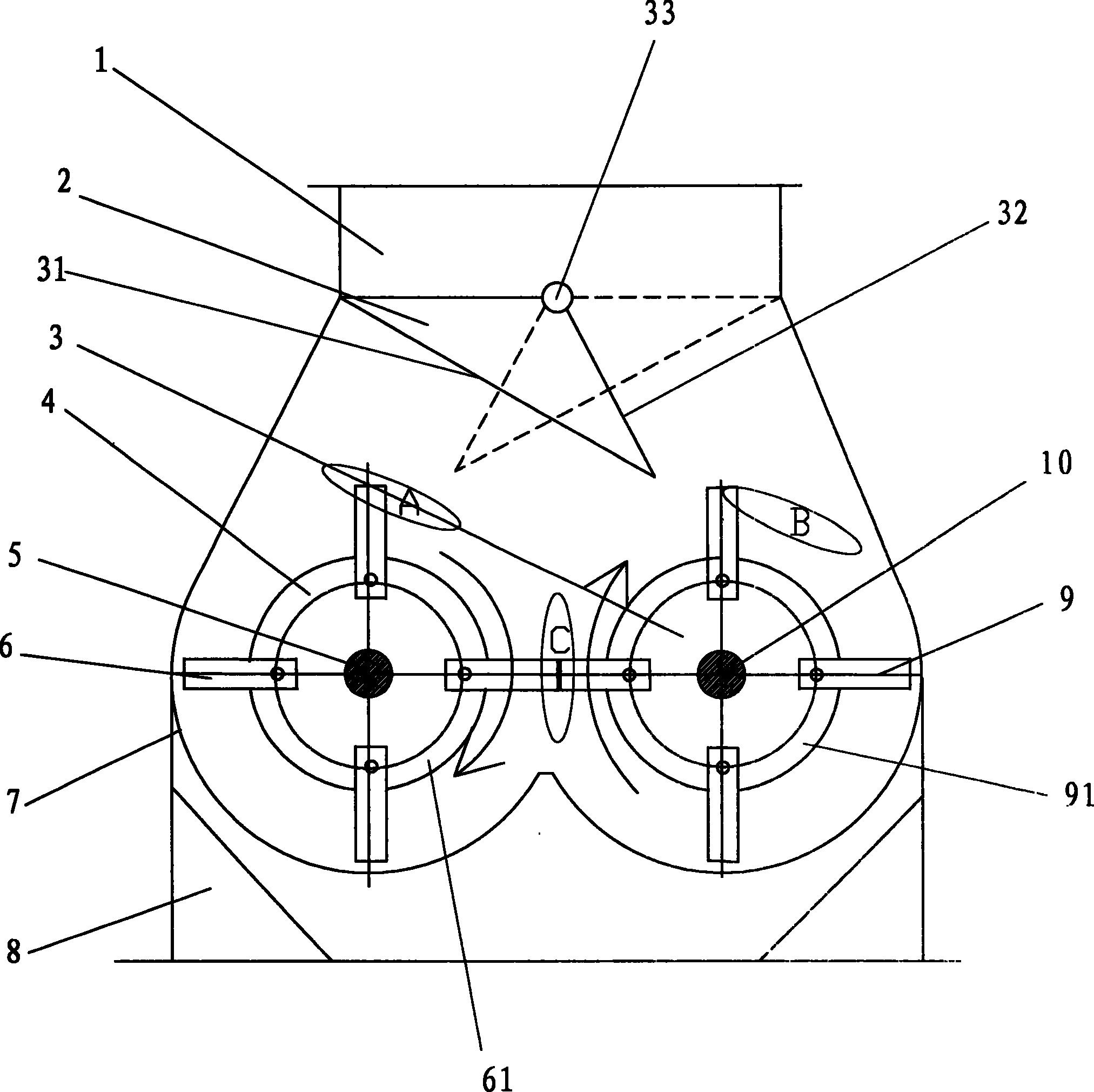
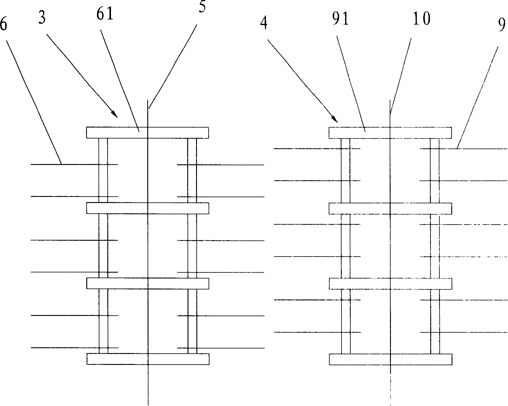
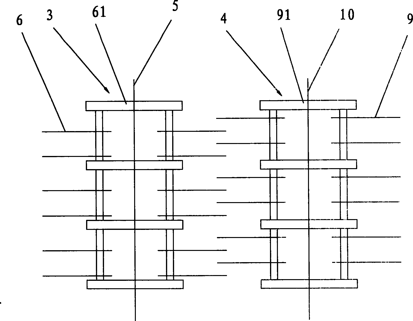
[0015] 1. Raw material import; 2. Material guiding device; 3. Right rotor assembly; 4. Left rotor assembly; 5. Left main shaft; 6. Left hammer; 61. Left hammer bracket; 7. Case ; 8, machine base; 9, right hammer; 91, right hammer support; 10, right main shaft; 31, retaining surface; 32, guide surface; 33, rotating shaft.

[0016] See figure 1 , figure 1 It is a schematic cross-sectional structure diagram of an embodiment of the present invention; it is a double-rotor hammer mill, including a feed inlet 1, a guide device 2, a machine base 8, a casing 7 and rotor assemblies 3, 4 , the casing 7 is located on the machine base 8, the feed inlet 1 is located on the casing 7, and two horizontal rotor assemblies 3, 4 parallel to each other are arranged in the casing 7; the two rotor assemblies 3, 4 The hammers 6 and 9 are located on the ha...


PUM


Abstract

The invention provides a dual-rotor hammer slice crusher, comprising a material inlet 1, a material guide device 2, a machine foundation 8, a casing 7 and two rotor assemblies 3 and 4. the casing 7 is arranged on the machine foundation 8; the material inlet 1 is arranged on the casing 7 which is internally provided with the two rotor assemblies 3 and 4 which are horizontally parallel to each other; the hammer slices 6 and 9 of the two rotor assemblies 3 and 4 are axially staggered; the cross-section of the material guide device 2 is a isosceles triangle with a material retaining surface 31 atthe end face and material guide surfaces 32 at the two bevels; the top angle of the material guide device 2 is movably positioned on the material inlet 1 by a rotary shaft 33. The invention is provided with two high-efficiency crushing areas A and B, and an ultra-high efficiency crushing area C; when the hammer head of the hammer slices axially staggered with the dual-rotor assembly has partial superposition, the highest relative linear speed between material and the hammer slices can reach 2 times of the designed hammer slice speed, thus greatly improving crushing efficiency.

Description

technical field [0001] The invention relates to a hammer mill, in particular to a feed port with a guide device, a machine base, a casing and a rotor assembly, the casing is located on the machine base, and the feed port is located on the casing hammer mill. Background technique [0002] Most of the existing hammer mills in the market, whether domestic or imported, have a single-rotor structure. In order to improve the crushing efficiency of the pulverizer, it is usually used to increase the diameter of the rotor to increase the linear speed of the hammer. At present, the single-rotor hammer mill, due to the limitation of structural design and material strength, the maximum linear speed of the hammer has reached 100 meters per second, and the safety factor of the material is already very low. If you want to further improve the hammer The line speed is already very dangerous. Therefore, there is no good way to further improve the working efficiency of the single rotor pulv...

Claims


Application Information

Patent Timeline
Patent Type & Authority Patents(China)
IPC IPC(8): B02C13/20B02C13/28B02C13/286B02C13/26B02C13/284
Inventor 姜新民
Owner TIANMEN JINJIANG FOOD MACHINERY
Why Eureka
Try Eureka