

Flat surface active shielded gradient coil preparation method
A technology of shielding coils and gradient coils, which is applied in the direction of measuring devices, measuring magnetic variables, instruments, etc., can solve the problem of less available space
- Summary
- Abstract
- Description
- Claims
- Application Information
AI Technical Summary
Problems solved by technology
Method used
Image

Examples
Embodiment
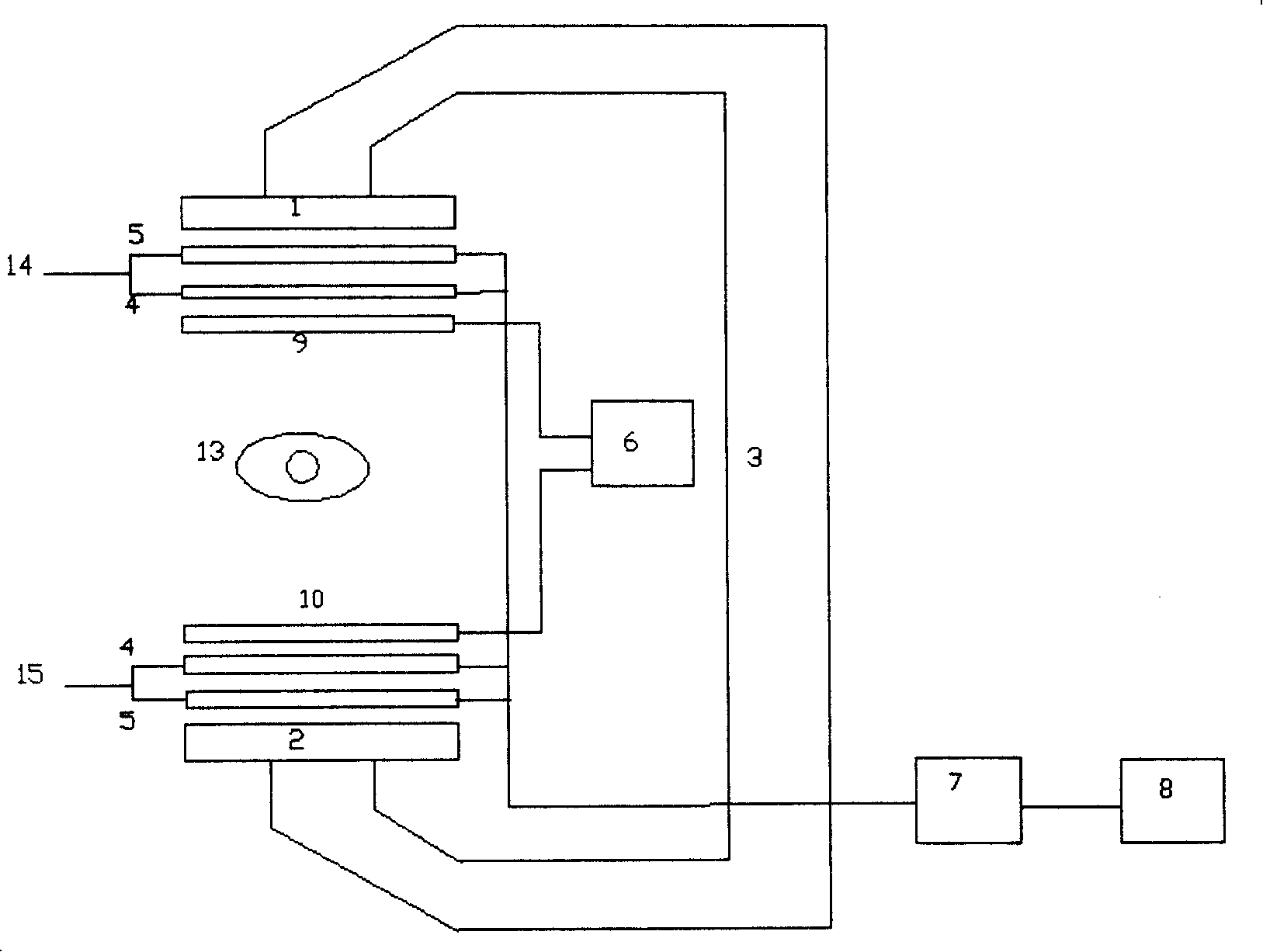
[0082] 1. Calculate the current distribution function of the active coil according to the known field distribution and the method of the target field.
[0083] 2. Add two shielding coils to the active coil, when the
[0084] F x ( s 1 ) ( k x , k z ) = - csch ( 2 k y d ) (8)
[0085] × { F x ( 1 ) ( k x , k z ) sinh [ ...
PUM
| Property | Measurement | Unit |
|---|---|---|
| Thickness | aaaaa | aaaaa |
| Thickness | aaaaa | aaaaa |
Abstract
Description
Claims
Application Information