
Touch panel

一种触摸板、薄膜的技术,应用在仪器、计算、电数字数据处理等方向,能够解决劣化显示器视觉辨认度等问题,达到视觉辨认度良好的效果

Inactive Publication Date: 2008-06-11
SMK CO LTD
View PDF1 Cites 8 Cited by
  • Summary
  • Abstract
  • Description
  • Claims
  • Application Information

AI Technical Summary

Problems solved by technology

[0005] However, in recent years, with the high-definition of liquid crystal displays, although the above-mentioned anti-glare treatment of particles of about several μm can suppress the external light from entering, but because the light from the liquid crystal has a finer pitch, the filler or its unevenness Flare that causes diffuse reflection of light from the liquid crystal, or color separation of liquid crystal pixels, sometimes significantly deteriorating the visibility of the display

Method used


Image

  • Touch panel
  • Touch panel
  • Touch panel

Examples


Embodiment Construction

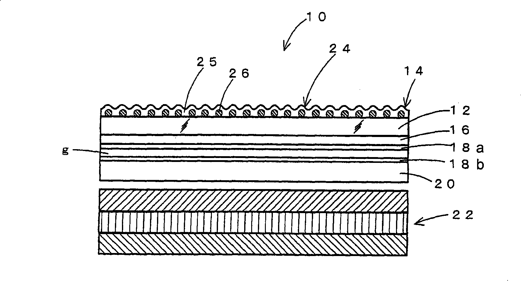
[0029] Embodiments of the present invention will be described below with reference to the drawings. figure 1 This shows the first embodiment of the present invention, and a touch panel 10 of this embodiment includes a touch panel film 14 formed of a transparent film base material 12 such as PET of about 180 to 200 μm, for example. On the back surface of the film 14 for a touch panel, a transparent electrode film 18 a such as an ITO film is formed in a predetermined pattern from the anchor layer 16 . The film 14 for the touch panel is fixed on the opposite surface of the catalyst plate substrate 20, and the transparent electrode film 18b is provided opposite to the transparent electrode film 18a on the catalyst plate substrate with a slight gap g. The touch panel substrate 20 is made of glass or transparent resin, and is fixed to the image surface of a display 22 such as liquid crystal.

[0030] For the film substrate 12 of the film 14 for a touch panel, for example, in additi...


PUM

PropertyMeasurementUnit
roughnessaaaaaaaaaa
particle diameteraaaaaaaaaa

Abstract

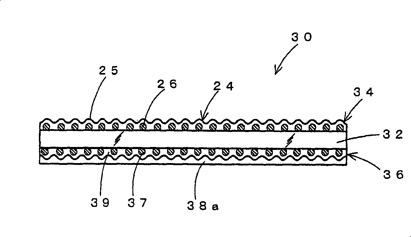
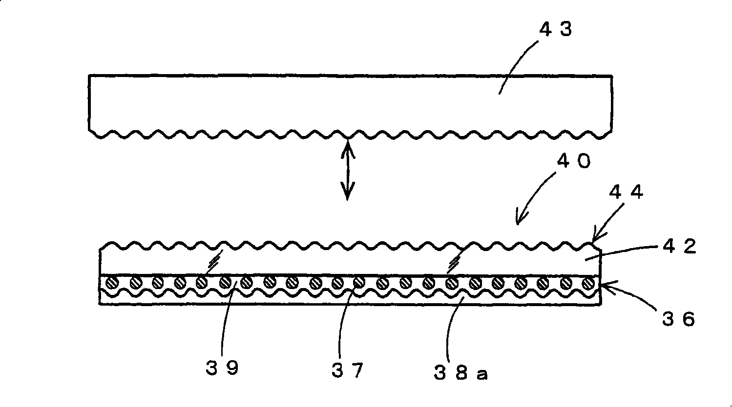
The invention provides a touch panel whose visual resolution is not decreased even using in an ultra-high resolution display, with a simple structure. The touch panel includes a transparent electrode film 18a made of ITO film or the like that is formed on a transparent film substrate 12. The surface of the film substrate opposite the surface on which the transparent electrode 18a is formed has a coating layer 24. The resin 25 of the coating layer 24 is provided with fillers 26 which are dispersed and arrayed about one layer evenly. The fillers 26 have an average particle size of 0.1 mum to 0.01 mum, and the coating layer is formed to have a surface having arithmetic particle roughness (Ra) of 0.1 mum to 0.01 mum, whereby the Ra of the surface of the coating layer is formed to 1 / 2000th to 1 / 4000th of the pixel pitch of a display to which the touch panel is attached.

Description

technical field [0001] The present invention relates to a touch panel used as an input device provided on the surface of a display or the like of various electronic devices. Background technique [0002] In recent years, electronic devices equipped with a touch panel displayed on a display are widely used. However, the surface of the touch panel is exposed to external light or external light, which affects the visibility of the display. Therefore, in order to avoid such a situation, the film for a touch panel is subjected to a surface treatment called an anti-glare treatment in which the surface of the film is roughened to scatter light and prevent it from entering. As a method of roughening the surface of the film, there is a method of applying and curing an ultraviolet curable resin obtained by dispersing fine particles called fillers to form irregularities of several μm. [0003] A touch panel 2 using such a film 1 for a touch panel is configured as shown in FIG. 4 . Th...

Claims


Application Information

Patent Timeline
Patent Type & Authority Applications(China)
IPC IPC(8): G02F1/133G06F3/041
CPCG06F3/045C09K2323/00
Inventor 江上武宏中村尚美
Owner SMK CO LTD
Learn More