Shutter glasses and image display system

a technology of image display system and shutter glasses, which is applied in the direction of optics, instruments, electrical appliances, etc., can solve the problems of observer feeling strange and observer feeling uncomfortabl

Inactive Publication Date: 2012-07-19
SEIKO EPSON CORP
View PDF5 Cites 4 Cited by
  • Summary
  • Abstract
  • Description
  • Claims
  • Application Information

AI Technical Summary

Benefits of technology

[0036]In the aspect of the invention, the image display system includes the shutter glasses that can switch both the left-eye selection part and the right-eye selection part to the transmission state when one of the image for left eye and the image for right eye is displayed and can switch both the left-eye selection part and the right-eye selection part to the blocking state when the other image is displayed, and thus, the same action and advantage as those of the above described shutter glasses may be enjoyed.

Problems solved by technology

That is, there is a problem that, in the above described position, the observer may feel uncomfortable.
Therefore, for example, when the observer tilts the face toward the right, if only the image for left eye is visually recognized with both eyes, the observer may feel strange.

Method used


Image

  • Shutter glasses and image display system
  • Shutter glasses and image display system
  • Shutter glasses and image display system

Examples


first embodiment

[0054]As below, the first embodiment of the invention will be explained with reference to the drawings.

Configuration of Image Display System

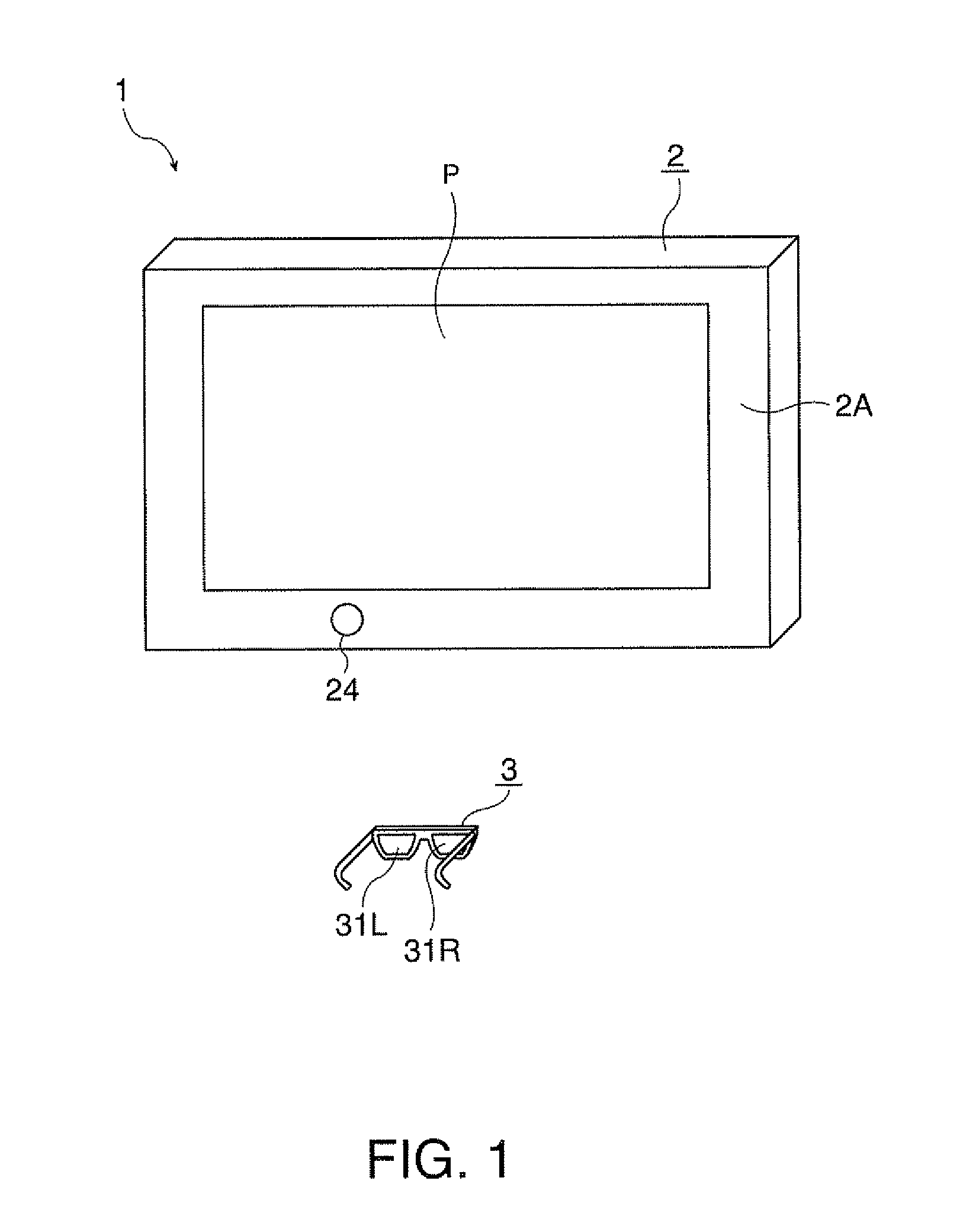
[0055]FIG. 1 is a perspective view showing a usage of an image display system 1.

[0056]The image display system 1 allows an observer to stereoscopically view displayed images, and includes a display device 2 as an image display device and shutter glasses 3 as shown in FIG. 1.

Configuration of Display Device

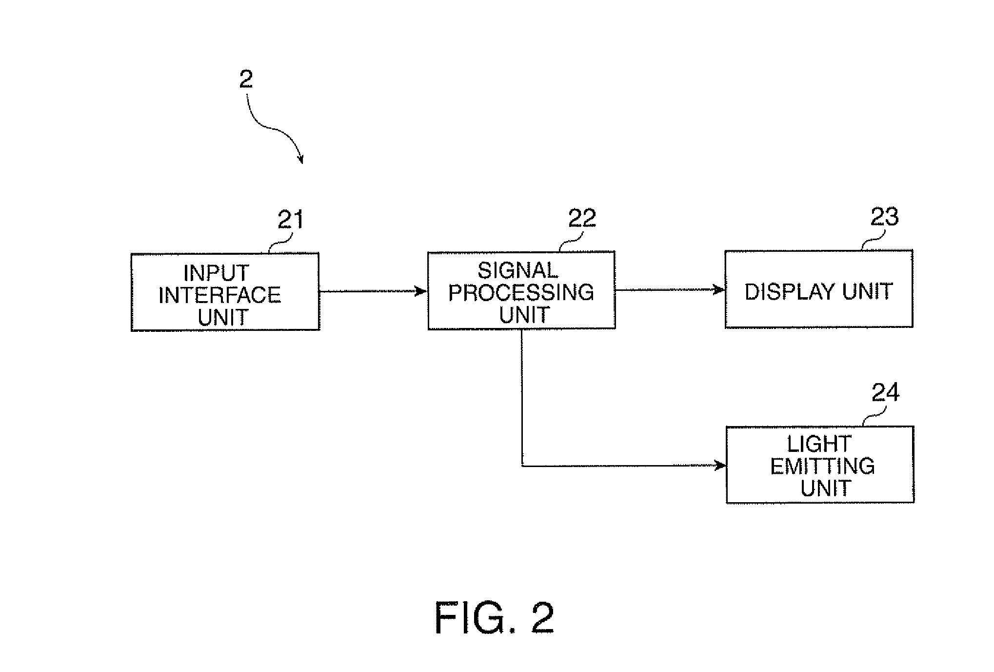
[0057]FIG. 2 is a block diagram showing a configuration of the display device 2.

[0058]The display device 2 displays images on a screen P (FIG. 1).

[0059]The display device 2 includes an input interface unit 21, a signal processing unit 22 as a control unit, a display unit 23, and a light emitting unit 24 as a signal output unit as shown in FIG. 2.

[0060]The signal processing unit 22 converts input signals externally input via the input interface unit 21 (FIGS. 5A and 5B) into predetermined signals and outputs them to the display unit 23 for time-d...

second embodiment

[0126]Next, the second embodiment of the invention will be explained with reference to the drawings.

[0127]In the following explanation, the same signs are assigned to the similar configuration and the same members as those of the first embodiment, and their detailed explanation will be omitted or simplified.

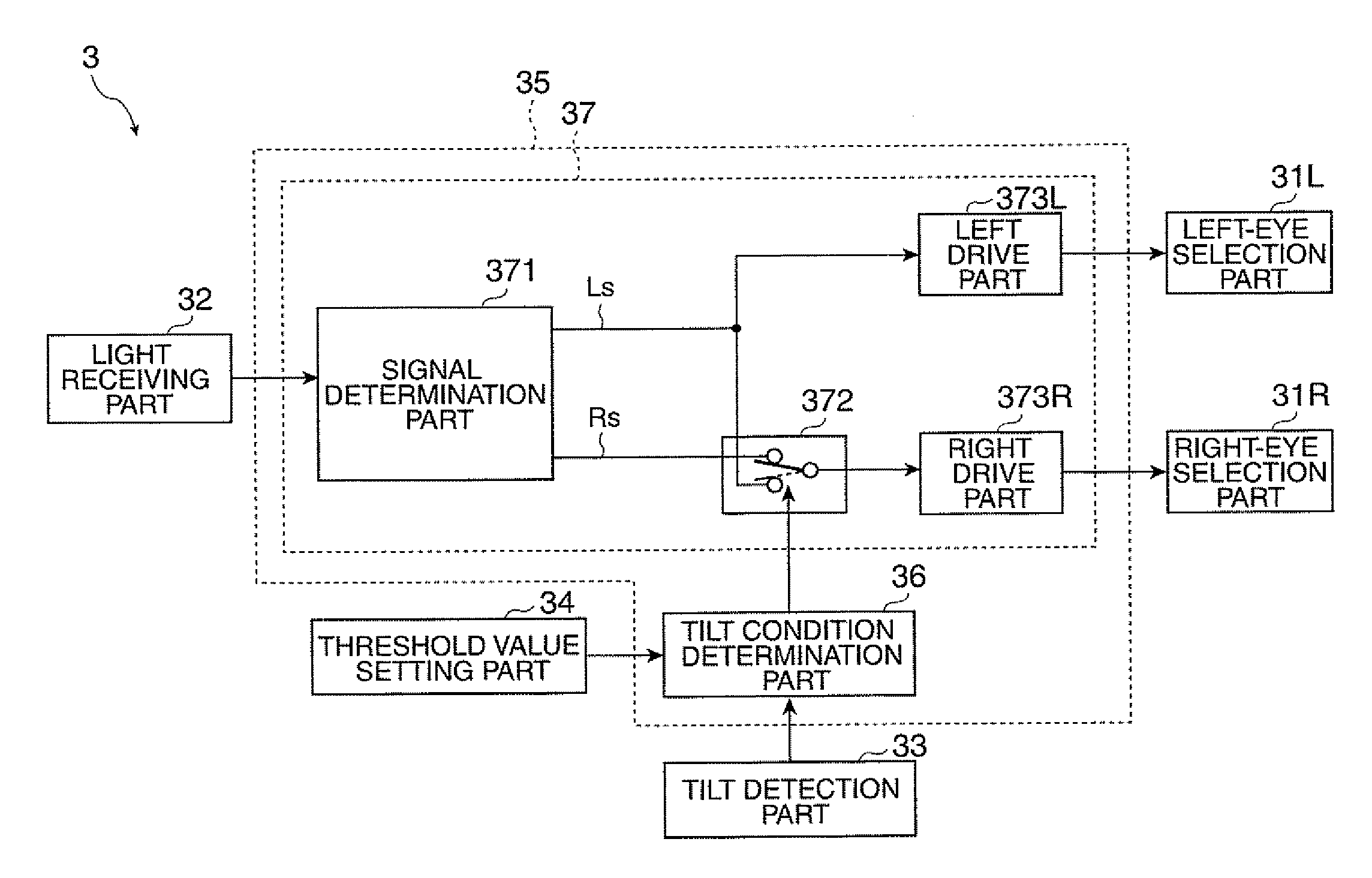
[0128]FIG. 6 is a block diagram showing a configuration of shutter glasses 3 in the second embodiment.

[0129]The embodiment is different only in the configuration of the shutter glasses 3 from the first embodiment as shown in FIG. 6.

[0130]Specifically, the shutter glasses 3 in the second embodiment is formed by adding a signal selection part 38 as a timing selection part and a second signal switching part 374 to the first embodiment as shown in FIG. 6.

[0131]The rest of the configuration is the same as that of the first embodiment.

[0132]The signal selection part 38 is a part operated by a user and receives selection such that the respective selection parts 31L, 31R are operated bas...

third embodiment

[0150]Next, the third embodiment of the invention will be explained with reference to the drawings.

[0151]In the following explanation, the same signs are assigned to the similar configuration and the same members as those of the second embodiment, and their detailed explanation will be omitted or simplified.

[0152]FIG. 8 is a block diagram showing a configuration of shutter glasses 3 in the third embodiment.

[0153]The embodiment is different only in the configuration of the shutter glasses 3 from the second embodiment as shown in FIG. 8.

[0154]Specifically, the shutter glasses 3 in the third embodiment are different from those of the second embodiment only in that the signal selection part 38 is omitted and the second signal switching part 374 operates based on an output signal S2 from the tilt condition determination part 36 as shown in FIG. 8. The rest of the configuration is the same as that of the second embodiment.

[0155]FIG. 9 is a block diagram showing a configuration of the tilt...


PUM


Abstract

Shutter glasses include a left-eye selection part and a right-eye selection part that respectively switch to a transmission state or a blocking state, a tilt detection part that detects a tilt condition of the shutter glasses, a tilt condition determination part that compares an output value of the tilt detection part and a predetermined threshold value, a signal acquisition part that acquires a left switch signal in synchronization with the image for left eye and a right switch signal in synchronization with the image for right eye, and a switching operation part that switches the left-eye selection part and the right-eye selection part to the transmission state or the blocking state. When the output value is equal to or more than the threshold value, the switching operation part switches both the left-eye and the right-eye selection parts in response to one of the left and the right switch signal.

Description

BACKGROUND[0001]1. Technical Field[0002]The present invention relates to shutter glasses and an image display system.[0003]2. Related Art[0004]In related art, an image display system (stereoscopic image display apparatus) including an image display device that displays images and shutter glasses worn by an observer for stereoscopic viewing of displayed images displayed in the image display device through the shutter glasses has been known (for example, see Patent Document 1 (JP-A-2009-232249).[0005]In the image display system disclosed in Patent Document 1, the image display device displays an image for left eye in a first display period and displays an image for right eye in a second display period, and time-divisionally and alternately displays the image for left eye and the image for right eye with respect to each display period.[0006]Further, the shutter glasses include the so-called liquid crystal shutters, and the left-eye shutter and the right-eye shutter alternately change b...

Claims


Application Information

Patent Timeline
Patent Type & Authority Applications(United States)
IPC IPC(8): G02B27/26G02B27/22G02B30/25
CPCG02B27/2264G02B27/26H04N2213/008H04N13/0454H04N13/0438G02B30/24G02B30/25H04N13/341H04N13/359
Inventor YONENO, KUNIO
Owner SEIKO EPSON CORP
Why Eureka
Try Eureka