Cylinder structure

A cylinder and arc structure technology, applied in the direction of fluid pressure actuating devices, etc., can solve the problems of difficult adjustment, difficult to guarantee the radial coaxiality of the cylinder, and scrapped products, etc., to improve the coaxiality of the radial plane, overcome the The effect of unstable factors and low production costs

Active Publication Date: 2008-06-18
NINGBO AIRTAC AUTOMATIC INDAL
View PDF0 Cites 8 Cited by
  • Summary
  • Abstract
  • Description
  • Claims
  • Application Information

AI Technical Summary

Problems solved by technology

[0002] As we all know, the cylinder body of most cylinders currently adopts round tubes. When fixing the trunnion brackets, most of these cylinders adopt the embracing fixing method, that is, the two brackets are symmetrically hugged and fixed on both sides of the cylinder. The cylinder of this structure is used. After a long time, due to the loosening of the fixing bolts, or the loosening of the cohesive contact surface after being pushed and pulled or squeezed and dented, under the impact of the reciprocating motion of the cylinder piston, the trunnion bracket will slide axially on the cylinder, and the trunnion bracket will slide on the cylinder. Sliding in the upper axis will cause the overall position of the cylinder to shift, causing the cylinder to deviate in position when moving forward and backward. In the light case, the automation equipment will fail to work and the product will be scrapped. In the severe case, it will endanger the safety of personnel or damage the overall equipment, resulting in major accidents.
At the same time, it is difficult to ensure the radial coaxiality of the cylinder after the trunnion bracket of the current cylinder is fixed, and it is also difficult to adjust, which affects the accuracy of the product

Method used


Image

  • Cylinder structure
  • Cylinder structure
  • Cylinder structure

Examples


Embodiment Construction

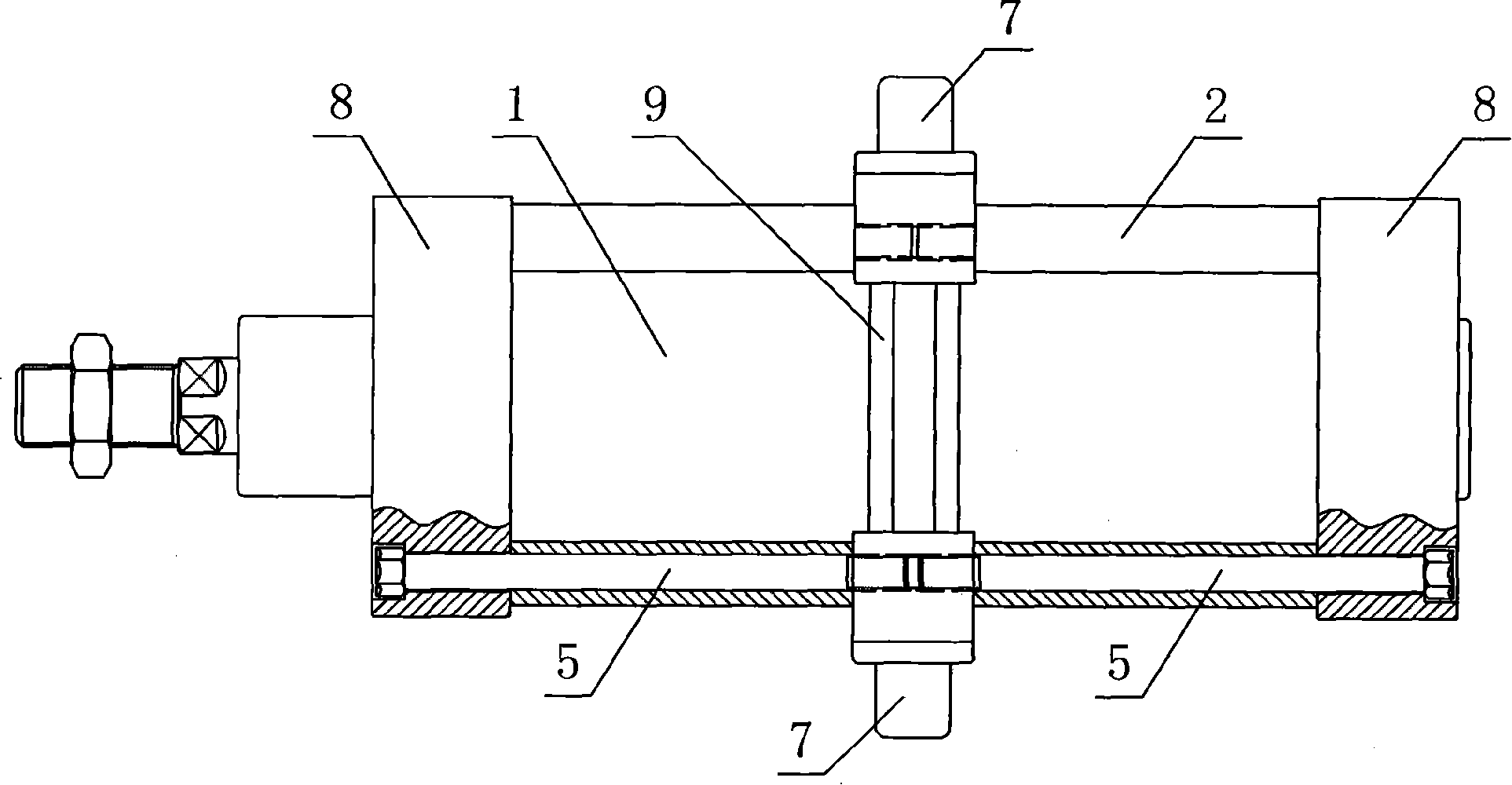
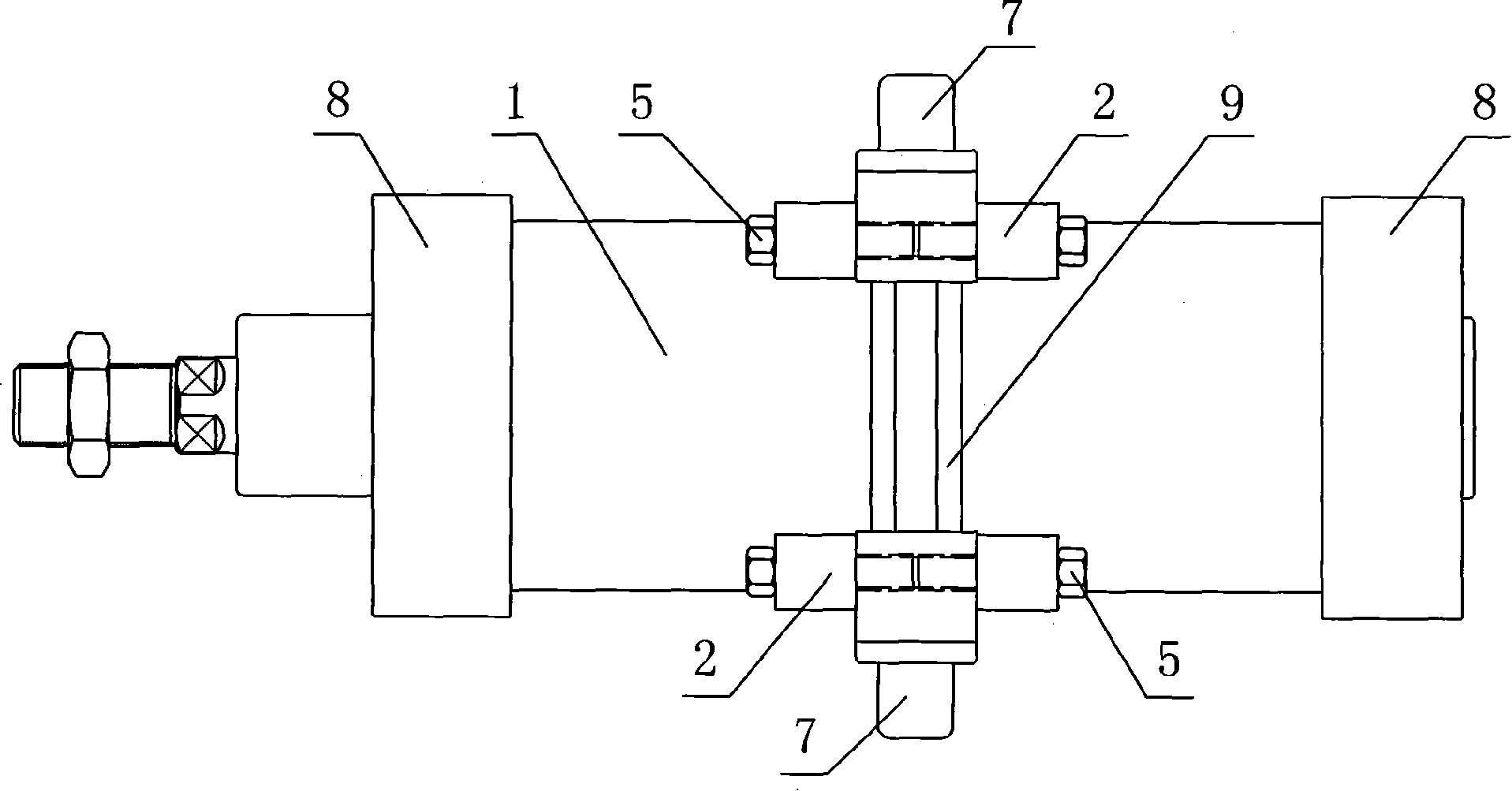
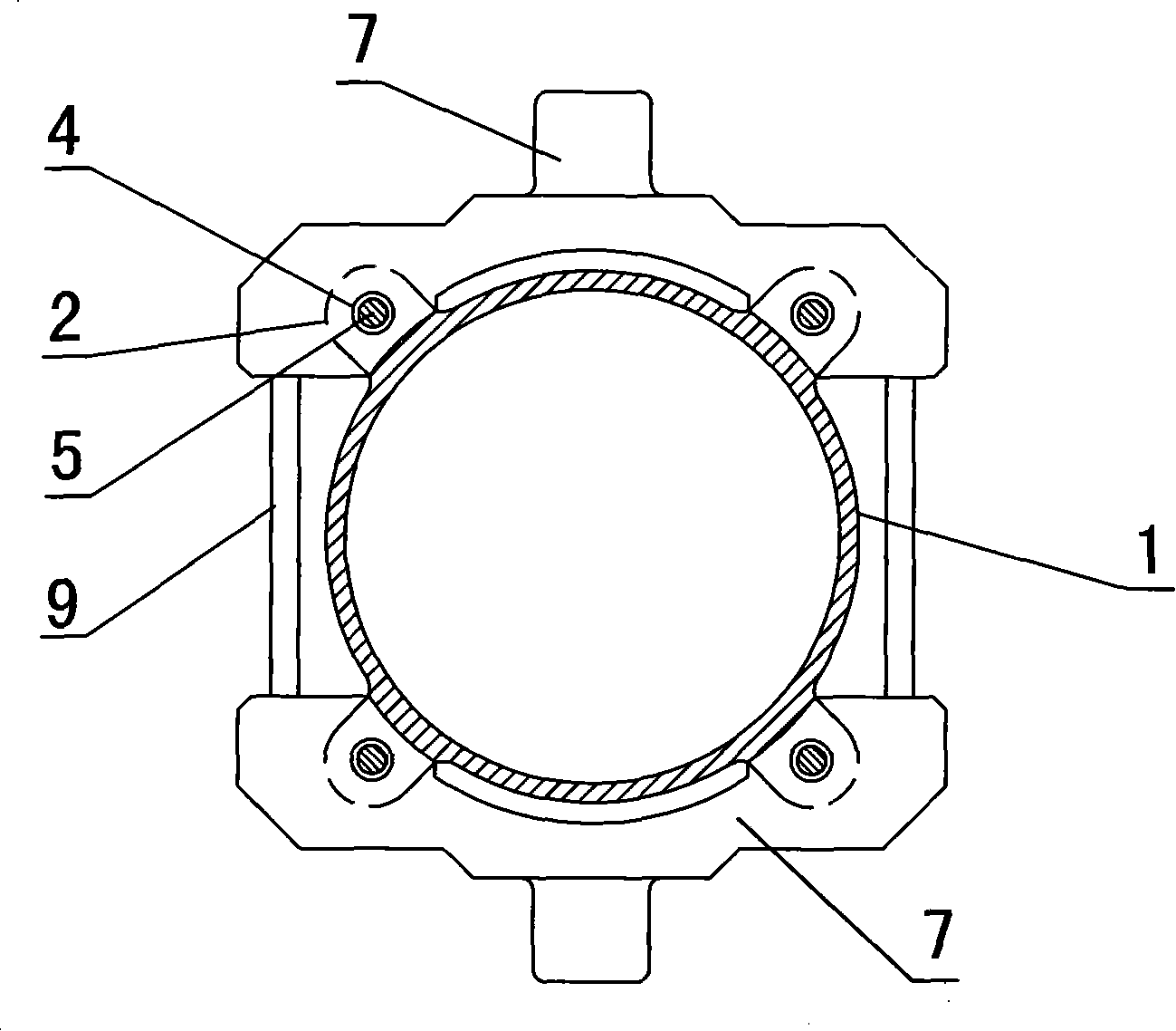
[0024] in such as figure 1 image 3 In the shown embodiment 1, lugs 2 are provided on the outer wall of the cylinder block 1 along the axial direction of the cylinder block 1, and there are four lugs 2, which are symmetrically distributed around the cylinder block 1. The lugs 2 and the cylinder block 1, etc. Long, the lug 2 is provided with a mounting hole 4, and the middle of the lug 2 is provided with a gap 3 (see Figure 4 ), the two sides of the notch 3 are perpendicular to the axis of the cylinder body 1, the width of the notch 3 is consistent with the thickness of the trunnion bracket 7, the trunnion bracket 7 is installed in the notch 3, and matches the mounting hole 4 in the lug 2 The fixed screw rod 5 passes through the front and rear end covers 8 of the cylinder, the lugs 2 and the trunnion bracket 7 (see Figure 7 ) connected. The trunnion brackets 7 are symmetrically arranged on both sides of the cylinder body 1, and are arched structures. The trunnion 71 is arr...


PUM


Abstract

The invention discloses an air cylinder structure. The air cylinder consists of a cylinder body, end covers arranged at the two ends of the cylinder body and a trunnion mounting arranged on the cylinder body. The outer wall of the cylinder body is provided with lugs along the axial direction of the cylinder body. Mounting holes are arranged in the lugs. The lugs provided with the trunnion mounting are provided with nicks and the trunnion mounting is mounted in the nicks. Fixed screws drill through the lugs to be connected with the trunnion mounting. The invention effectively solves the problems that the trunnion mounting of the existing air cylinder sliding along the axial direction on the air cylinder causes the shift of the air cylinder and position deviation when the air cylinder moves forward or backward. The problems can cause the invalidation of the automation equipment and the scrapping of the products, even endangering personal security or damaging the whole equipment and causing a heavy accident. The invention has simple structure, convenient operation, low production cost and is worthy of promotion.

Description

technical field [0001] The invention relates to a cylinder, in particular to a cylinder structure. Background technique [0002] As we all know, the cylinder body of most cylinders currently adopts round tubes. When fixing the trunnion brackets, most of these cylinders adopt the embracing fixing method, that is, the two brackets are symmetrically hugged and fixed on both sides of the cylinder. The cylinder of this structure is used. After a long time, due to the loosening of the fixing bolts, or the loosening of the cohesive contact surface after being pushed and pulled or squeezed and dented, under the impact of the reciprocating motion of the cylinder piston, the trunnion bracket will slide axially on the cylinder, and the trunnion bracket will slide on the cylinder. Sliding in the upper axis will cause the overall position of the cylinder to deviate, causing the cylinder to deviate in position when moving forward and backward. In the light case, it will cause the automati...

Claims


Application Information

Patent Timeline
Patent Type & Authority Applications(China)
IPC IPC(8): F15B15/20
Inventor 王世忠
Owner NINGBO AIRTAC AUTOMATIC INDAL
Why Eureka
Try Eureka