
Rotary rail device

A technology for connecting devices and tracks, which is applied in the field of electronic communication, and can solve problems such as non-compliance, inability to adjust at will, and too fixed video head

Inactive Publication Date: 2008-06-25
BEIJING SHANGXING WEISHI INFORMATION +1
View PDF0 Cites 4 Cited by
  • Summary
  • Abstract
  • Description
  • Claims
  • Application Information

AI Technical Summary

Problems solved by technology

[0002] 1. The range of motion of the camera in the prior art is almost zero, and it is too fixed and lacks mobility. The result of the lack of mobility makes it impossible for the camera to move in a wider area
[0003] 2. The current display screen does not have a camera installed in the upper frame, nor does it have a moving slot or moving rail for the camera, which is a deficiency of the background technology
[0004] 3. The existing camera is fixed, and it cannot be adjusted at will when it is connected to one position, which will bring great inconvenience to the user, and the user cannot transmit or receive the video effect of the other party very well
[0005] The video header is too fixed and does not conform to the principle of people-oriented
[0006] 4. The existing cameras are all on the top of the screen during the use of the Internet, which has a very big defect. During the video chat, the other party sees our avatar, instead of looking straight up but looking up. The reason is The camera is at the top of the screen, so our avatar is captured from top to bottom, so the other party feels that they can only see our hair or the top of the head, and our face does not give the other party a positive feeling. The video effect of this is very bad

Method used


Image

  • Rotary rail device

Examples


Embodiment Construction

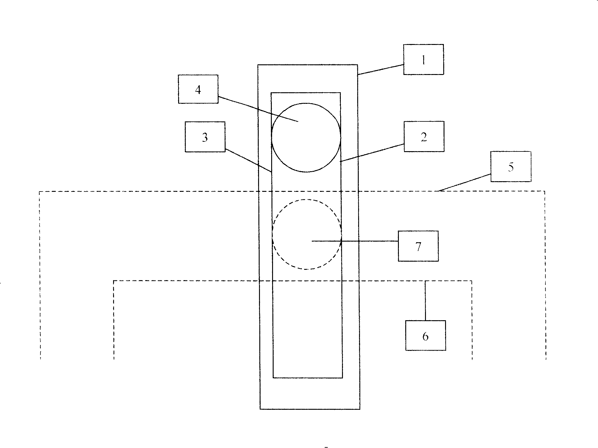
[0030] 1. A rotating rail device, which has a clamping rail for the camera, the clipping rail is used to make the camera move in the rail, and the clipping rail and the display are connected by a connecting device.

[0031] 2. A rotating rail device, the connecting device between the rail and the display is a rotating shaft, which is used to rotate the rail relative to the display.

[0032] 3. A rotating rail device, the range of rotation is 90° to 180°.

[0033] 4. A rotating rail device, the range of rotation is 180° to 360°.

[0034] 5. A rotating rail device, a slot device is connected to the upper frame of the display screen, and a camera is placed in the slot to ensure the movement of the camera.

[0035] 6. A rotating rail device, the rail groove has a device connected to the upper frame of the display screen.

[0036] 7. A rotating rail device, the rail groove protruding from the plane of the upper frame.

[0037] 8. A rotating rail device, which has a track for pla...


PUM


Abstract

The invention provides a rotary-rail device relating to the electronic communication field, which is characterized in that: the invention is provided with a clamping control rail allowing a camera to move in the rails, wherein the clamping control rail is connected with a display through a connecting device.

Description

Technical field: [0001] The invention relates to the field of electronic communication, and provides a rotating rail device. Background technique: [0002] 1. The range of motion of the camera in the prior art is almost zero, and it is too fixed and lacks mobility. As a result of the lack of mobility, the camera cannot be moved in a wider area. [0003] 2. The current display screen does not have a camera installed in the upper frame, nor does it have a moving slot or a moving rail for the camera, which is a deficiency of the background technology. [0004] 3. The existing camera is fixed and cannot be adjusted arbitrarily when it is connected in one position, and this will bring great inconvenience to the user, and the user cannot propagate or receive the video effect of the other party well. [0005] The video header is too fixed and does not conform to the principle of people-oriented. [0006] 4. The existing cameras are all on the top of the screen during the use of t...

Claims


Application Information

Patent Timeline
Patent Type & Authority Applications(China)
IPC IPC(8): G06F1/16H04N5/225
Inventor 张逶
Owner BEIJING SHANGXING WEISHI INFORMATION
Learn More