
Method for manufacturing microphone diaphragm

A manufacturing method and microphone technology, applied to electrical components, sensors, etc., can solve problems such as low production efficiency, inconsistent product performance parameters, film damage, etc., and achieve high production efficiency

Inactive Publication Date: 2008-06-25
SHENZHEN HORN AUDIO
View PDF0 Cites 21 Cited by
  • Summary
  • Abstract
  • Description
  • Claims
  • Application Information

AI Technical Summary

Problems solved by technology

[0006] It can be seen from the above procedures that the existing processes of bonding film rings and cutting film rings need to be manually operated, resulting in low production efficiency, especially in the production of square film rings and mucous membranes, the efficiency is lower; and more importantly, manual work is easy. Causes membrane damage and creates inconsistent product performance parameters

Method used


Image

  • Method for manufacturing microphone diaphragm
  • Method for manufacturing microphone diaphragm

Examples


Embodiment Construction

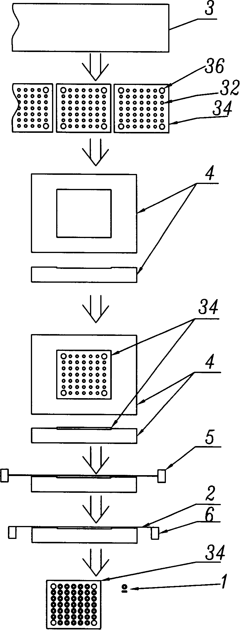
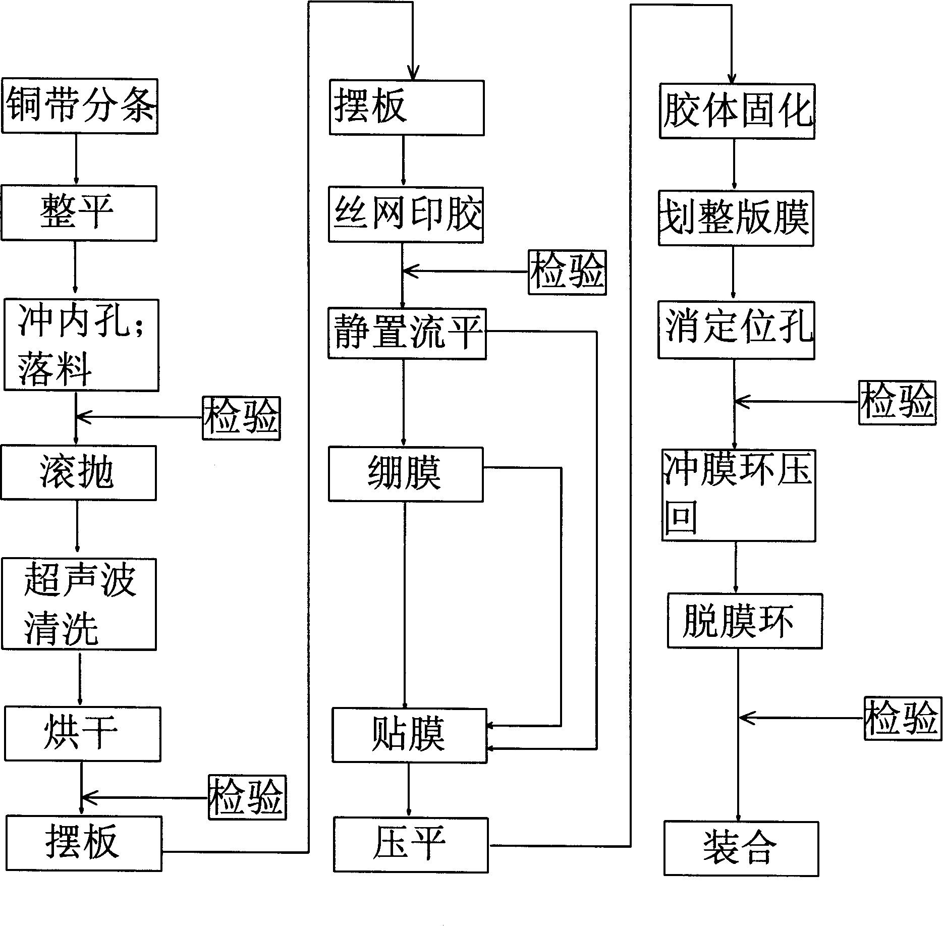
[0027] see figure 1 and figure 2 , the microphone diaphragm 1 of the present invention comprises a film ring (not shown in the figure) and the film 2 that is stuck on the film ring, and the film 2 is pasted on the metal diaphragm plate by a specific process method (see below for details), and then The film ring with the film 2 attached is punched out from the metal film plate. The diaphragm 1 requires good electrical conductivity and adhesive strength between the diaphragm 2 and the metal diaphragm plate, so as to ensure a high flatness of the diaphragm 2 and realize array formation and high-efficiency production. The specific steps of manufacturing the above diaphragm 1 are as follows:

[0028] (1) Firstly, the metal strip 3 with a certain thickness that can be used to make the film ring is properly slit to be divided into metal strips of a certain size (not shown in the figure), and then precisely leveled.

[0029] (2) Slitting the metal strip into strips, punching out t...


PUM


Abstract

The invention provides a manufacturing method of a microphone vibration membrane, which has the concrete steps that (1) a proper metal material belt is selected for carrying on that a whole plate impacts an inner hole of a membrane ring, and a whole piece of a membrane plate is formed after blanking, (2) an adhesive, which is used for sticking a membrame, and is printed at peripheries of the inner hole on the surface of the membrane plate, (3) the surface of the membrane plate, which is stuck with the adhesive, is covered with a membrane, and is planished. After the membrane plate is pressed to thin, the adhesive is solidified, and has electrical conductivity, (4) through adopting that a stamping mould impacts for an outer diameter of the membrane ring for making the emebrane ring which is adhered to the membrane dropped from the membrane plate, so that the vibration membrane used in a microphone is obtained, and the vibration membrane is collected at last. By using the manufacturing method of the microphone vibration membrane, the invention has high production efficiency, damages of the membrane can not appear, and the problem that product property parameters are not uniform can not also occur.

Description

【Technical field】 [0001] The invention relates to a method for manufacturing components in an electroacoustic device, in particular to a method for manufacturing a microphone diaphragm. 【Background technique】 [0002] In the electro-acoustic industry, the microphone is usually stacked by dust-proof net, shell, diaphragm, gasket, back electrode, cavity, copper ring, circuit board, impedance conversion part, etc., and then packaged by edge-sealing process of. Among them, the diaphragm and the diaphragm ring that make up the diaphragm are bonded together by a special adhesive to form a whole, and its manufacturing process is segmented processing, as follows: [0003] (1) Stamping to make film rings: put metal strips (copper or other metal alloys) in a stamping die and stamp them into ring-shaped metal sheets as film rings. The inner diameter and outer diameter of the membrane ring are determined according to product requirements. [0004] (2) Adhesive film ring: After the si...

Claims


Application Information

Patent Timeline
IPC IPC(8): H04R31/00
Inventor 孙贵平黎祖志欧阳小禾
Owner SHENZHEN HORN AUDIO
Learn More