Sealing device

A technology for sealing devices and sealing components, which is applied in the directions of engine sealing, bearing assembly, transportation and packaging, etc. It can solve the problems of no radial interference, achieve small sliding torque, excellent sealing performance, and good resistance to muddy water Effect

Inactive Publication Date: 2008-06-25
NOK CORP
View PDF1 Cites 7 Cited by
  • Summary
  • Abstract
  • Description
  • Claims
  • Application Information

AI Technical Summary

Problems solved by technology

[0005] However, when the sealing lip is formed as described above by the first side lip 55a which is in close contact with the inner side end surface of the radially raised portion 52b of the oil slinger member 52 slidably, slidably with the same slinger When the second side lip 55d in close contact with the inner end surface of the radially raised portion 52b of the oil ring member 52 and the radial lip 55c arrang

Method used


Image

  • Sealing device
  • Sealing device
  • Sealing device

Examples


Embodiment Construction

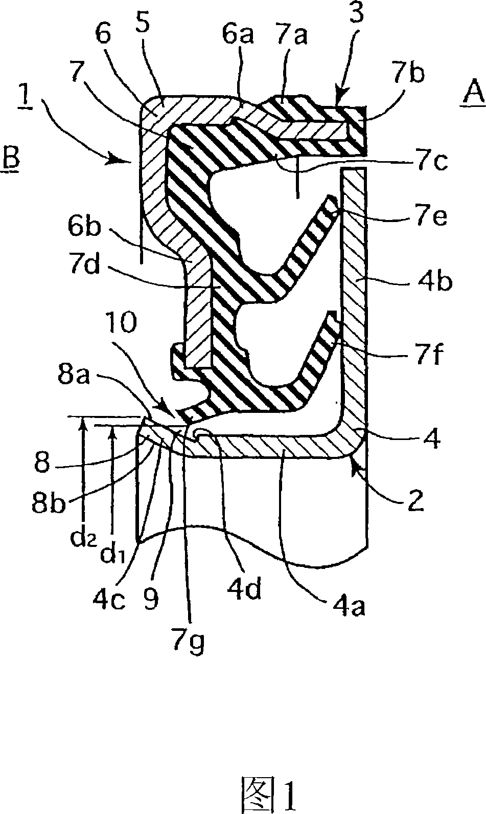
[0052] Hereinafter, embodiments of the present invention will be described with reference to the drawings.

[0053]FIG. 1 shows a cross section of a main part of a sealing device 1 according to an embodiment of the present invention. The sealing device 1 of this embodiment is used as a hub bearing seal (hub seal) in the field of automobiles, and is configured as follows.

[0054] That is, first, this sealing device 1 has an inner bearing inner ring (an inner peripheral side mounting member, not shown in the figure) that is one of two members that rotate relatively, and rotates together with the inner ring of the bearing. a peripheral side seal member 2; and a non-rotatable outer peripheral side seal member 3 installed in a bearing outer ring (outer peripheral side mounting member, not shown in the figure) which is the other of the two members.

[0055] The inner peripheral side seal member 2 is composed of an oil slinger member (hereinafter simply referred to as an oil slinge...


PUM


Abstract

A sealing device (1) formed by combining an inner peripheral sealing member (2) and an outer peripheral sealing member (3), where the inner peripheral sealing member (2) such as a slinger member is prevented from falling out in axially one direction from the outer peripheral sealing member (3) such as a lip seal member. The inner peripheral sealing member (2) has a metal ring (4) provided with a tubular section (4a) and a radially rising section (4b) integrally formed with the tubular section (4a) and extending radially outward from one end of the tubular section (4a). The outer peripheral sealing member (3) has side lips (7e, 7f) in slidable intimate contact with the radially rising section (4b) of the metal ring (4), and also has a radial lip (7g) provided without contact, on the outer peripheral side of the tubular section (4a) of the metal ring (4). The tubular section (4a) has an axial fall-out prevention section (8) having an outer diameter d 2 greater than the inner diameter d 1 of the radial lip (7g) and preventing the metal ring (4) from falling out in axially one direction from the outer peripheral sealing member (3).

Description

technical field [0001] The invention relates to a sealing device related to sealing technology. The sealing device of the present invention can be used as a wheel hub bearing seal in the fields related to automobiles or in general machinery and the like. Background technique [0002] Conventionally, a sealing device 51 shown in FIG. 4 is known. The sealing device 51 consists of an oil flinger member (inner peripheral side) mounted on an inner peripheral mounting member (such as an inner ring) 61 of one of two relatively rotating members (such as an inner ring and an outer ring of a bearing) 61,62. seal) 52 and a lip seal member (outer peripheral side seal) 53 attached to an outer peripheral mounting member (for example, an outer ring) 62 as the other side. [0003] The oil slinger member 52 is made of metal material, and on one axial end of the cylindrical portion 52a, an annular radially raised portion 52b is integrally formed to form a substantially L-shaped cross sectio...

Claims


Application Information

Patent Timeline
IPC IPC(8): F16J15/32F16C33/78F16C33/80F16J15/447
CPCF16J15/3268F16C2326/02F16J15/3256F16C33/7879F16J15/3264F16C33/7883F16C33/7816F16C2240/70F16C2240/40F16C41/04F16J15/32F16C33/78F16J15/447F16C33/80
Inventor 神前刚
Owner NOK CORP
Why Eureka
Try Eureka