
Touch control component positioning structure

A touch element and positioning mechanism technology, applied in electrical elements, telephone structures, transmission systems, etc., can solve problems such as increasing the manufacturing cost of electronic devices, limiting component configuration, and falling off, achieving high industrial utilization value, and improving the ease of falling off. Effect

Inactive Publication Date: 2008-07-02
INVENTEC CORP
View PDF0 Cites 0 Cited by
  • Summary
  • Abstract
  • Description
  • Claims
  • Application Information

AI Technical Summary

Problems solved by technology

[0004] However, in order to make a closed slot on the assembled casing of the electronic device, it usually needs to be molded twice, which will increase the manufacturing cost of the electronic device
[0005] Moreover, the slots used to position the touch elements in electronic devices in the past only use friction to position the touch elements, but after long-term use, the touch elements will be difficult to locate in the slot due to wear and tear, and even prone to fall-off accidents
[0006] Furthermore, some electronic devices have special configurations of internal components, and setting slots on the assembly case will limit the configuration of components.

Method used


Image

  • Touch control component positioning structure
  • Touch control component positioning structure

Examples


Embodiment Construction

[0036] Embodiments of the present invention are described below through specific examples, and those skilled in the art can easily understand other advantages and effects of the present invention from the content disclosed in this specification.

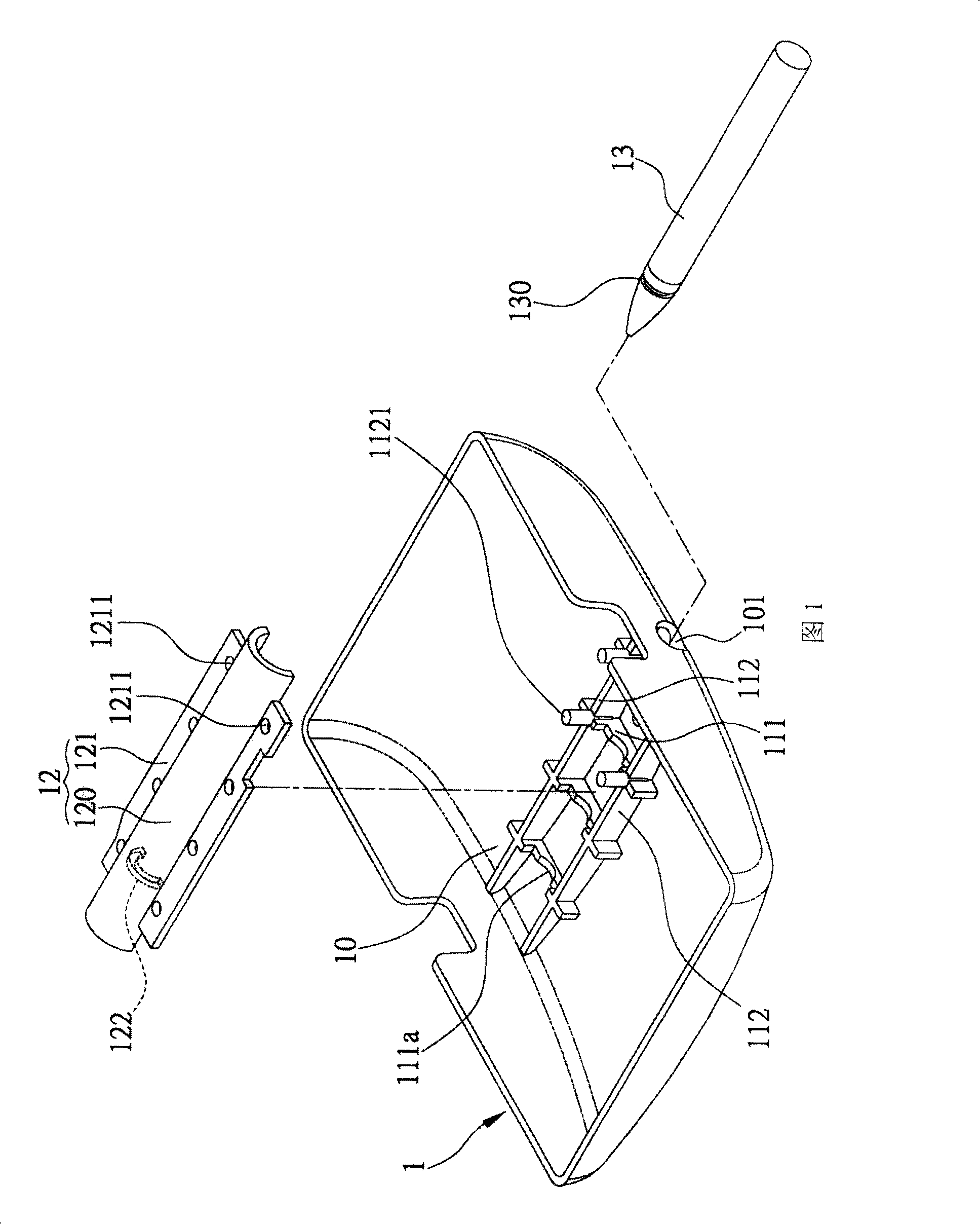
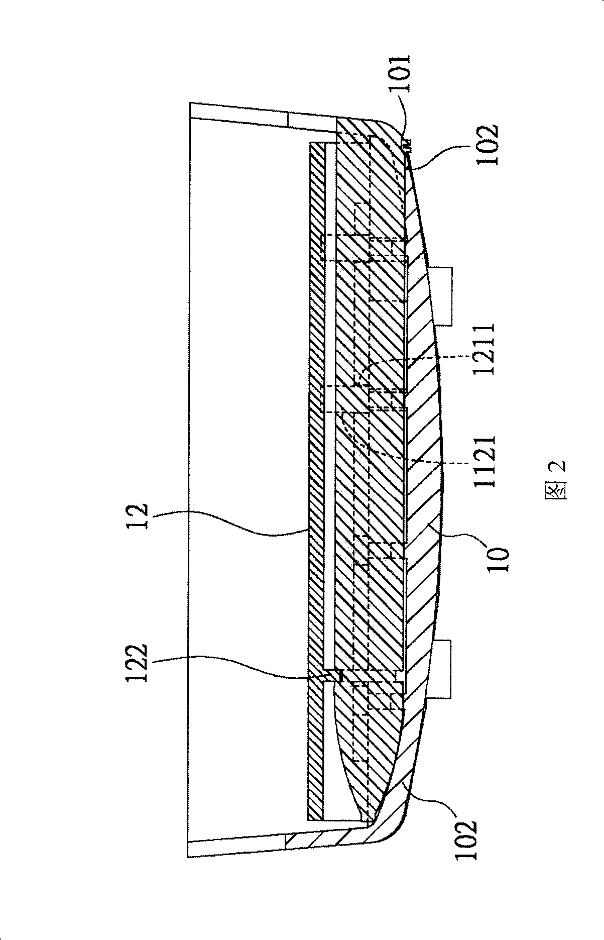
[0037] Please refer to FIG. 1, the positioning mechanism of the touch element of the present invention is used to position the touch element 13 on the chassis bottom plate 10 of the electronic device 1. The positioning mechanism includes: a support frame 11, which is arranged on the chassis bottom plate 10, There are a plurality of beam parts 111, and the first joint plate part 112 arranged on both sides of the beam part 111; the fixed frame 12 has a fixed body 120, and is arranged on both sides of the fixed body 120 and is combined with the first joint The second combined plate portion 121 of the plate portion 102; the accommodating unit is arranged between the beam portion 101 of the support frame 11 and the fixed body 120 of the fi...


PUM


Abstract

The invention discloses a positioning mechanism of a touch control element, which is used for positioning the touch control on a bottom board of a casing of an electronic device. The positioning mechanism comprises a support frame that is arranged on the bottom board of the casing and provided with a plurality of beam parts and a first combined board part arranged at the two sides of the beam parts; a fixed frame that is provided with a fixed body and a second combined board part arranged at the two sides of the fixed body and combined with the first combined board part; a holding unit that is arranged between the beam parts of the support frame and the fixed body of the fixed frame to hold the touch control element; a snap-fit unit that is arranged between the fixed body of the fixed frame and the touch control element to snap and fix the touch control element between the fixed frame and the support frame.

Description

field of technology [0001] The present invention relates to a positioning mechanism, more specifically, to a positioning mechanism of a touch element. Background technique [0002] Such as personal digital assistants (PDAs) and business-type mobile phones are all electronic devices that are convenient for modern people to carry with them. For the convenience of users, the above-mentioned electronic devices are all equipped with touch elements. In the shape of a pen, the user can click or even write on the screen of the electronic device. [0003] In order to store touch elements, manufacturers provide slots on the casing of the electronic device, and the slot is usually manufactured together with one of the assembled casings of the electronic device. [0004] However, in order to make a closed slot on the assembly case of the electronic device, usually two mold openings are required, which will increase the manufacturing cost of the electronic device. [0005] Moreover, th...

Claims


Application Information

Patent Timeline
IPC IPC(8): H04Q7/32H04B1/38H04M1/02
Inventor 杨振峰王乃贤
Owner INVENTEC CORP
Learn More