Novel anti-shake pan-tilt for camera and anti-shake method

A camera, anti-shake technology, applied in image communication, machine/stand, TV and other directions, can solve problems such as image blur, achieve fast response speed, large anti-shake angle, and overcome the effect of magnet interference

Pending Publication Date: 2021-09-03
辽宁中蓝光电科技有限公司
View PDF7 Cites 3 Cited by
  • Summary
  • Abstract
  • Description
  • Claims
  • Application Information

AI Technical Summary

Problems solved by technology

[0004] The purpose of the present invention is to provide a novel camera anti-shake platform and anti-shake method with a reasonable structure and reliable use, so as to solve the problem that the existing camera lens anti-shake device cannot eliminate the imaging blur caused by the shaking and rotation of the lens in multiple directions It can realize the function of multi-axis anti-shake with large load and large angle. It has the advantages of fast response speed, strong load capacity, large anti-shake angle, and anti-electromagnetic interference, which greatly improves the imaging quality.

Method used


Image

  • Novel anti-shake pan-tilt for camera and anti-shake method
  • Novel anti-shake pan-tilt for camera and anti-shake method
  • Novel anti-shake pan-tilt for camera and anti-shake method

Examples


Embodiment 1

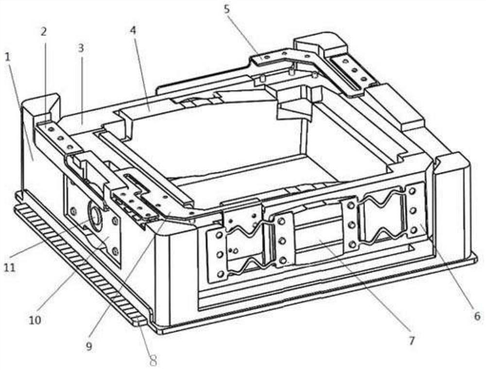
[0047] Such as Figure 1-Figure 16 As shown, a new camera anti-shake pan head includes a base 1, a protective case 12, a frame unit, a vibrator unit, a preload unit and a signal position sensing unit.

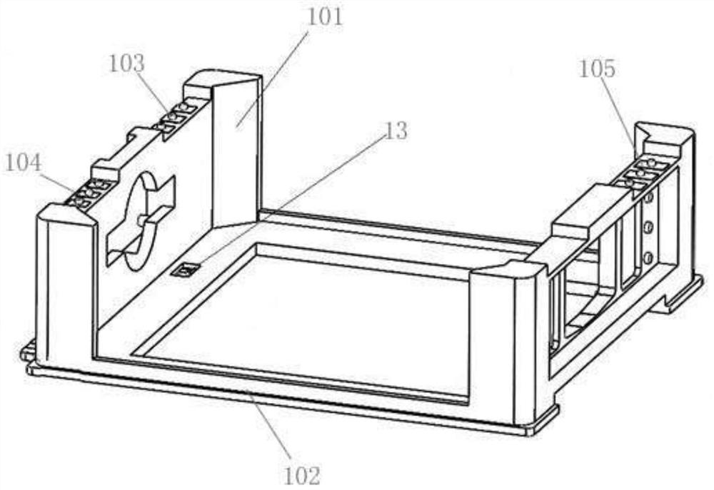
[0048] Wherein, the base 1 includes a base plate 102 and a retaining wall 101 arranged on the base plate 102. In this embodiment, the base plate 102 is a rectangular frame structure, the middle part is empty, and the number of retaining walls 101 is two. 102 is relatively arranged, the bottom plate 102 and the retaining wall 101 are built with metal strips for increasing strength, power taking and signal transmission, and the edge of the bottom plate 102 is provided with a conductive terminal lead-out area 8 connected to the metal strip, and the retaining wall 101 is provided with three conductive connection parts 103, 104, 105 of the metal strip.

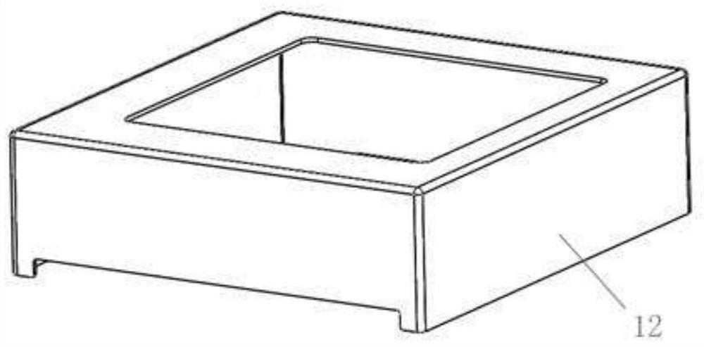
[0049] The protective shell 12 is buckled together with the base 1 to form a cavity that defines and protects.

[0050] The fram...

Embodiment 2

[0062] In this embodiment, the fixing method of the first ring piezoelectric ceramic vibrator assembly and the second ring piezoelectric ceramic vibrator assembly in the vibrator unit is the same as that of the first preload assembly and the second preload assembly in the preload unit. The fixed method is interchanged.

[0063] Take the interchangeable fixing method of the first ring piezoelectric ceramic vibrator assembly and the first preload assembly as an example:

[0064] The two sides of the fixed plate I are respectively connected and fixed with the retaining wall 101 by means of the leaf spring I, and the stepped shaft I11 is not provided in the first ring piezoelectric ceramic vibrator assembly, and the rotary support structure I in the embodiment is arranged on the fixed plate I Between the outer frame 3; the pre-pressing plate I in the first pre-pressing assembly is fixedly connected to the retaining wall 101, and the center is provided with a stepped shaft I11, and...

Embodiment 3

[0068] In this embodiment, the rotary support structure I between the inner side of the pre-pressing plate I and the side wall of the outer frame 3 is different from that in Embodiment 1. The slewing support structure Ⅰ abandons the matching structure of the arc groove and the ball, and adopts a number of elastic metal bending parts to realize the pre-compression function. At the same time, the elastic metal bending parts have the function of elastic deformation and do not affect the outer frame 3 There is a relative displacement with the retaining wall 101.

[0069] Others are the same as embodiment 1.


PUM


Abstract

The invention relates to a novel anti-shake pan-tilt for a camera and an anti-shake method. According to the technical key points, the novel anti-shake pan-tilt for the camera comprises a base, a protective shell, a frame unit, a vibrator unit, a pre-pressing unit and a signal position sensing unit, wherein the frame unit comprises an outer frame located at the inner side of the base and an inner frame arranged at the inner side of the outer frame; the vibrator unit comprises an annular piezoelectric ceramic vibrator assembly for enabling the outer frame to rotate along a first shaft relative to the base and a second annular piezoelectric ceramic vibrator assembly for enabling the inner frame to rotate along a second shaft relative to the outer frame; the first annular piezoelectric ceramic vibrator assembly is arranged between a retaining wall of the base and the side wall of the outer frame; the second annular piezoelectric ceramic vibrator assembly is arranged between the other side wall of the outer frame and the side wall of the inner frame; and the first shaft is perpendicular to the second shaft . According to the novel anti-shake pan-tilt for the camera, the problem that an existing anti-shake device for a pick-up lens cannot eliminate imaging blurring caused by shake and rotation of the lens in multiple directions, the anti-shake pan-tilt has the advantages of being high in response speed, high in load capacity, large in anti-shake angle, resistant to electromagnetic interference and the like, and the imaging quality is greatly improved.

Description

technical field [0001] The invention relates to the technical field of camera automatic focusing, in particular to a novel camera anti-shake platform and anti-shake method, which are suitable for mobile camera equipment. Background technique [0002] Because the voice coil motor has the advantages of simple structure, small size, low energy consumption, no noise, high acceleration, fast response, accurate displacement and low price, so for the automatic focusing device of the camera, the automatic focusing of the voice coil motor The function is still the most cost-effective solution. By fixing the optical lens on the voice coil motor drive carrier, the carrier acts as the power unit for lens movement, and connects the voice coil motor carrier and the housing through an elastic structure. When the motor is energized, the carrier will move linearly along the optical axis of the lens, thereby Realize automatic focus function. [0003] At present, the anti-shake device of the...

Claims


Application Information

Patent Timeline
Patent Type & Authority Applications(China)
IPC IPC(8): F16M11/04F16M11/12F16M11/18H04N5/232G03B17/56
CPCF16M11/04F16M11/121F16M11/18G03B17/561H04N23/687
Inventor 王全岭吴发权
Owner 辽宁中蓝光电科技有限公司
Why Eureka
Try Eureka