Control device with shift position detector

A detection device and control device technology, applied in transmission control, transmission parts, components with teeth, etc., can solve the problem of not achieving sufficient compactness of the ECU structure

Inactive Publication Date: 2008-07-09
AISIN AW CO LTD
View PDF1 Cites 2 Cited by
  • Summary
  • Abstract
  • Description
  • Claims
  • Application Information

AI Technical Summary

Problems solved by technology

However, the shift position detection sensor disclosed in the above-mentioned publication is integrated in the ECU structure, and this r

Method used


Image

  • Control device with shift position detector
  • Control device with shift position detector
  • Control device with shift position detector

Examples


Example Embodiment

[0143] Hereinafter, the preferred mode of implementing the present invention will be described with reference to the drawings.

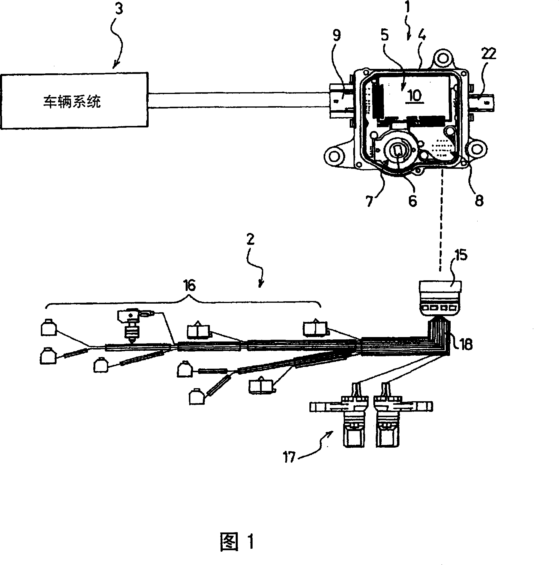
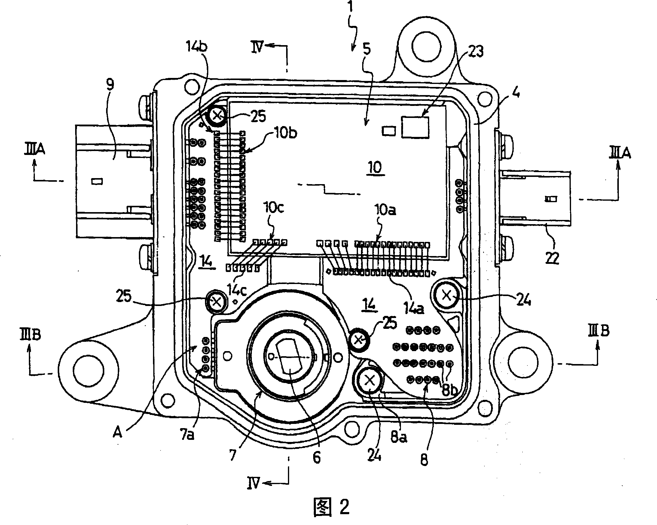
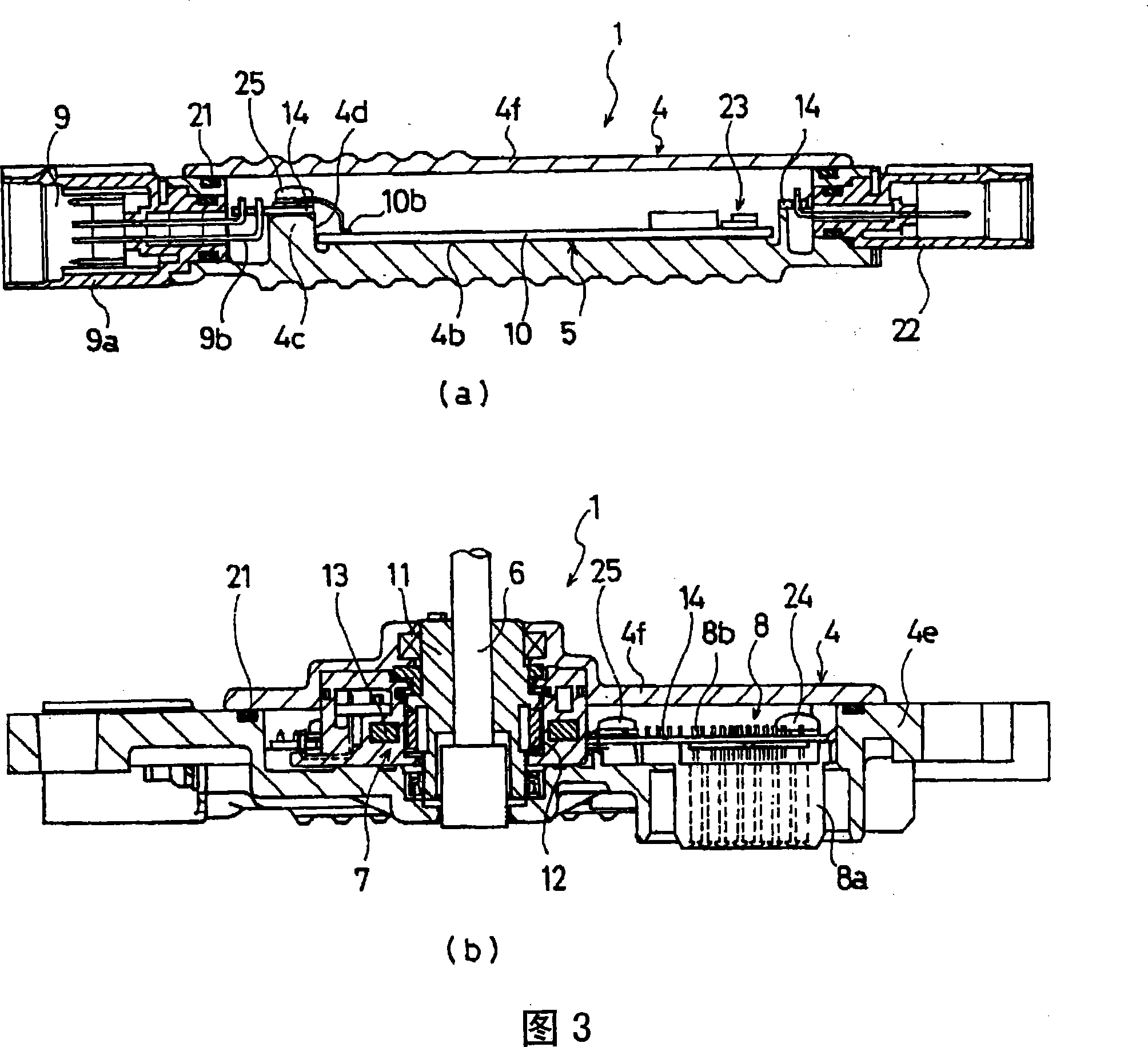
[0144] Fig. 1 shows a schematic diagram of the A / T intermediate electrical connection structure of one of the power trains of the first example of the embodiment of the control device with a shift position detecting device according to the present invention, and Fig. 2 shows the first example with shifting The plan view of the control device of the position detection device, FIG. 3 shows a cross-sectional view along the line III-III in FIG. 2, and FIG. 4 shows a schematic diagram of the control device with a shift position detection device in the first example, and (a) is the line along the line in FIG. The cross-sectional view along the IV-IV line, (b) is a partially enlarged cross-sectional view in (a). The shift position here refers to: for example, parking gear (P), reverse gear (R), neutral gear (N), drive gear (D), and so on. In addition, although ...


PUM


Abstract

A control device with a shifting position detecting device integrates a shifting position detecting device which detects the shifting position that changes according to the operation of the driver and a control device arranged with a control substrate that is used for controlling a plurality of elements of the power transmission system at least according to the detecting signal of the driving state, and accommodates the two devices in the box body, the control device of the invention comprises a connector part connected with the exterior electrical equipment, the shifting position detecting part and the connector part are parallel arranged at one side near the control substrate.

Description

[0001] This application is a divisional application of the application number "03801006.2", the application date is March 27, 2003, and the title of the invention is "control device with shift position detection device and power transmission system with the device". technical field [0002] The present invention relates to a shift position inspection device that detects a shift position shifted according to a driver's operation, and an electronic control device (hereinafter referred to as an ECU) capable of controlling a power train at least based on a detected signal of a vehicle running state. ), and a control device with a shift position detection device for the power train integrated with the connector connected to the external electrical equipment of the box. Here, the power train refers to an engine as a driving device, an automatic transmission (hereinafter referred to as A / T) that automatically performs engine operation / shift operation, a semi-automatic transmission tha...

Claims


Application Information

Patent Timeline
IPC IPC(8): F16H59/04F16H61/00F16H57/00F16H63/42
Inventor 村上直隆小笠原直人铃木研司福田笃高松淳
Owner AISIN AW CO LTD
Why Eureka
Try Eureka