Control device with shift position detector

一种检测装置、控制装置的技术,应用在传动装置控制、带有齿的元件、皮带/链条/齿轮等方向,能够解决没有做到ECU结构充分紧凑化等问题

Inactive Publication Date: 2011-05-25
AISIN AW CO LTD
View PDF8 Cites 0 Cited by
  • Summary
  • Abstract
  • Description
  • Claims
  • Application Information

AI Technical Summary

Problems solved by technology

However, the shift position detection sensor disclosed in the above-mentioned publication is integrated in the ECU structure, and this requirement is not specifically considered, and the structure of the ECU with the shift position detection device is not fully compacted.

Method used


Image

  • Control device with shift position detector
  • Control device with shift position detector
  • Control device with shift position detector

Examples


Embodiment Construction

[0144] Hereinafter, the preferred modes of implementing the present invention will be described in conjunction with the accompanying drawings.

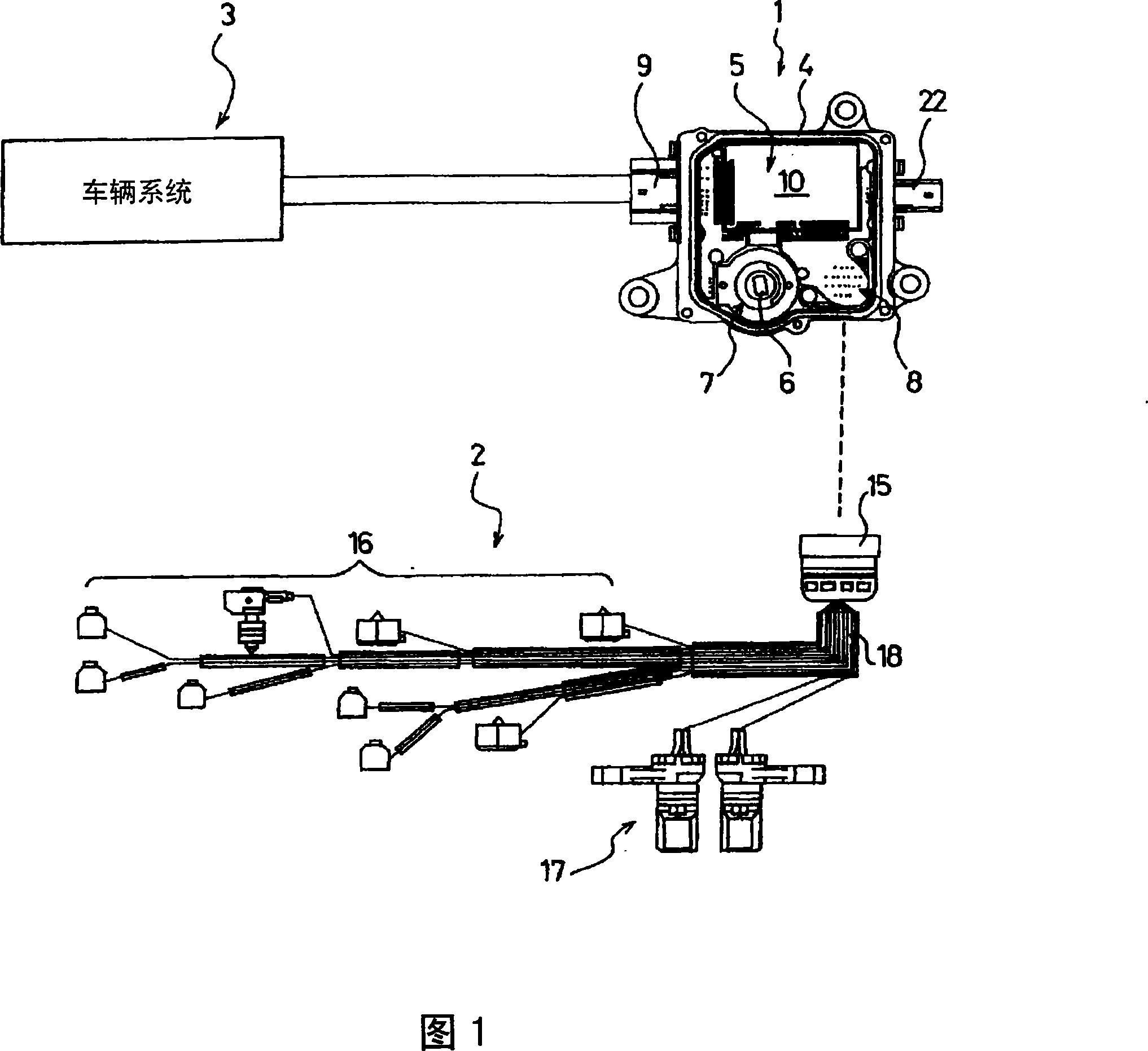
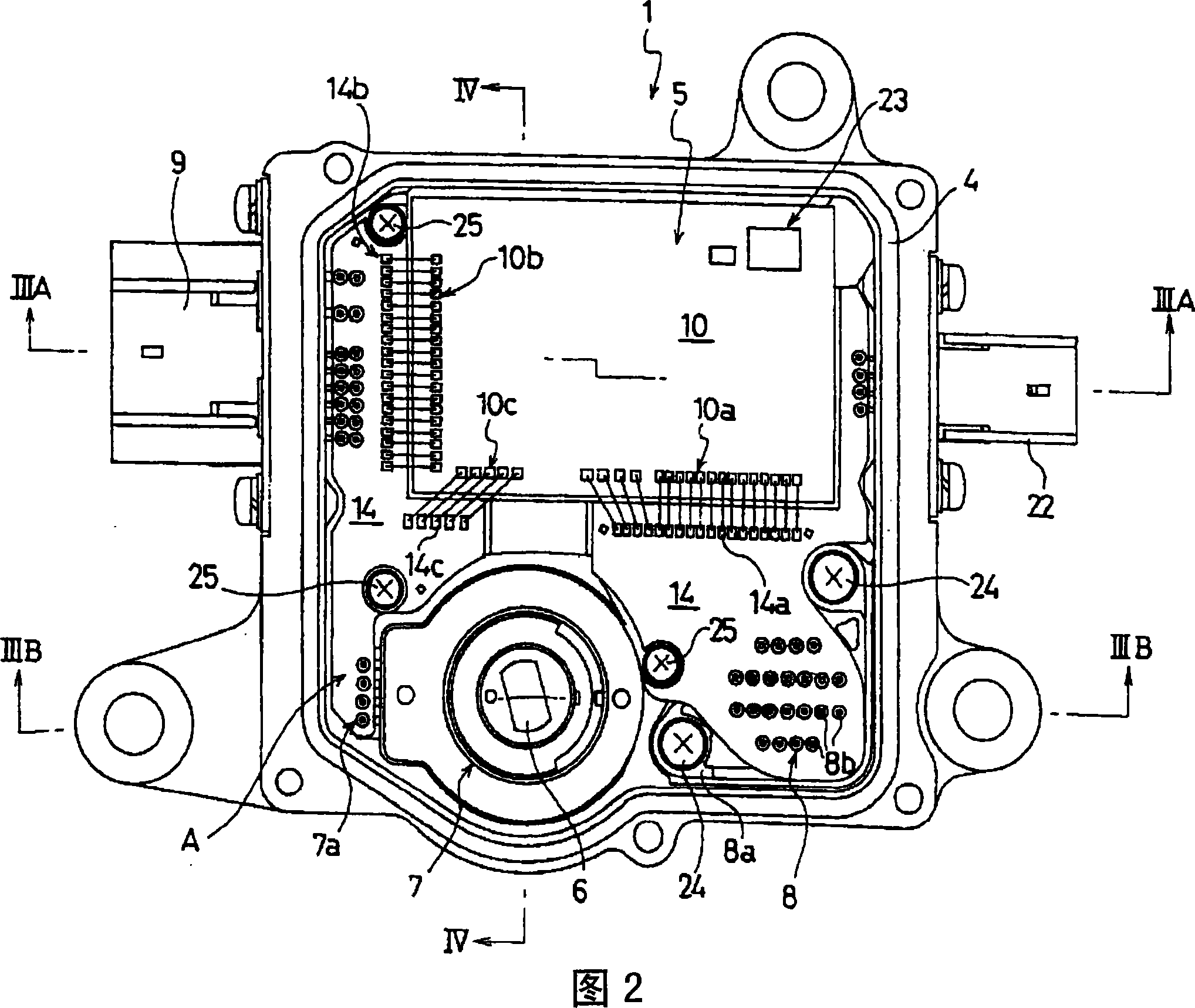
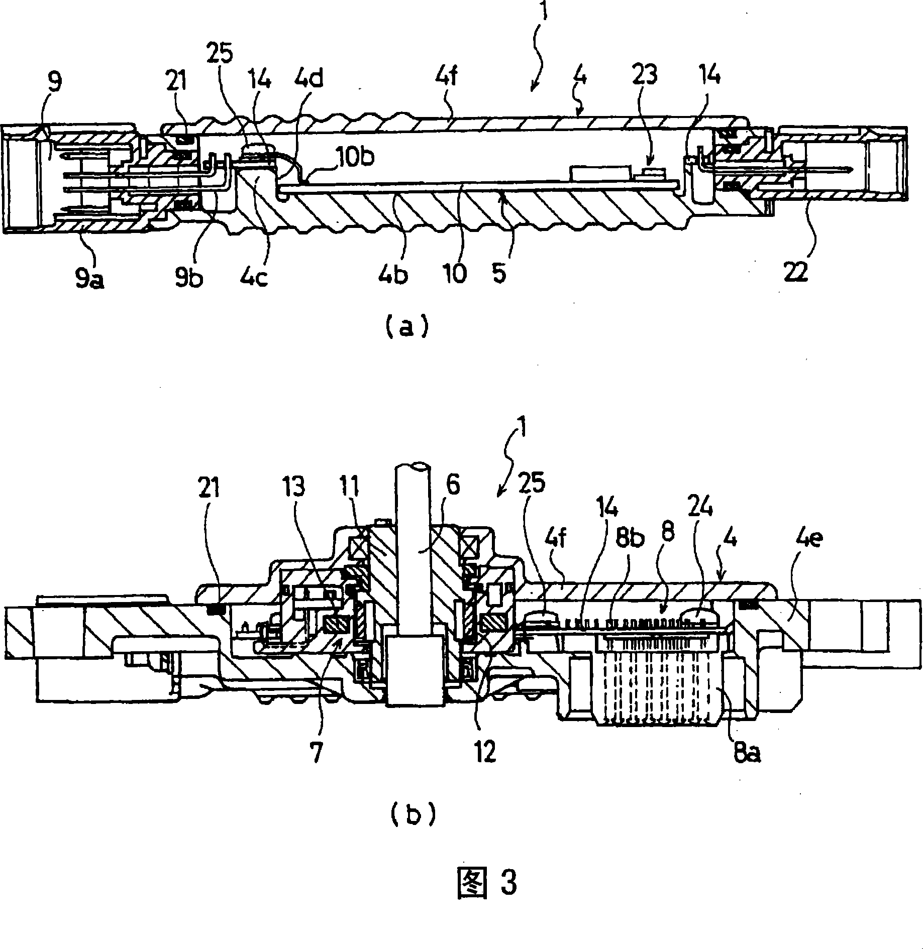
[0145]Fig. 1 shows a schematic diagram of the electrical connection structure in the A / T of one of the power trains of the first example of the embodiment of the control device with a shift position detection device according to the present invention, and Fig. 2 shows the first example of the control device with a shift position detection device. The plan view of the control device of the position detection device, Fig. 3 shows the sectional view along the III-III line in Fig. Section view of line IV-IV, (b) is a partially enlarged section view in (a). Here, the shift positions refer to: for example, park gear (P), reverse gear (R), neutral gear (N), drive gear (D) and the like. Also, the arrangement structure of the permanent magnet and the magnetic sensor of the shift position detection device shown in Fig. 4 (a), (b), although it ...


PUM


Abstract

A control device which comprises a shifting position detecting device in the present invention contains the following components in the box body: a shifting position detecting device which detects the shifting position that changes according to the operation of the driver; and a control device which comprises a control substrate that is used for controlling a plurality of elements of the power transmission system at least according to the detecting signal of the driving state; the control substrate is formed by the easy-manufacturing material and the shifting position detecting device is electrically connected with the control substrate.

Description

[0001] This application is a divisional application of the application number "03801006.2", the application date is March 27, 2003, and the title of the invention is "control device with shift position detection device and power transmission system with the device". technical field [0002] The present invention relates to a shift position inspection device that detects a shift position shifted according to a driver's operation, and an electronic control device (hereinafter referred to as an ECU) capable of controlling a power train at least based on a detected signal of a vehicle running state. ), and a control device with a shift position detection device for the power train integrated with the connector connected to the external electrical equipment of the box. Here, the power train refers to an engine as a driving device, an automatic transmission (hereinafter referred to as A / T) that automatically performs engine operation / shift operation, a semi-automatic transmission tha...

Claims


Application Information

Patent Timeline
Patent Type & Authority Patents(China)
IPC IPC(8): H05K7/02F16H63/42
Inventor 村上直隆小笠原直人铃木研司福田笃高松淳
Owner AISIN AW CO LTD
Why Eureka
Try Eureka