
Electromagnetic flux converter simulated calibration apparatus

An electromagnetic flow and converter technology, which is applied in the direction of measuring devices, the application of electromagnetic flowmeters to detect fluid flow, and volume/mass flow generated by electromagnetic effects. problem, to achieve the effect of low cost, accurate calibration and precise voltage

Inactive Publication Date: 2010-08-11
ZHONGHUAN TIG
View PDF2 Cites 0 Cited by
  • Summary
  • Abstract
  • Description
  • Claims
  • Application Information

AI Technical Summary

Problems solved by technology

The electromagnetic flowmeter includes the electromagnetic flow sensor and the electromagnetic flow converter, which must be calibrated before leaving the factory. The electromagnetic flow converter is generally calibrated together with the electromagnetic flow sensor on the actual pipeline during the production process, that is, the real flow calibration method. , but the real-flow calibration method exists: A. The construction of the calibration device is complicated and expensive; B. The accuracy of the real-flow calibration cannot represent the actual accuracy used on site; , the patent No. CN1908599A "based on the point-by-point measurement of the electromagnetic flowmeter dry calibration method of the inner surface of the pipe section" and the patent No. CN1908598A "based on the point-by-point measurement of the plane magnetic field dry calibration method of the electromagnetic flowmeter" patent disclose the electromagnetic flow The dry calibration method of the sensor in the meter, but the calibration literature of the electromagnetic flow converter in the electromagnetic flow meter has not been seen. In addition, the electromagnetic flow converter and the electromagnetic flow sensor must be used together. With the increasing application of electromagnetic flowmeter Widely, how to improve the interchangeability of electromagnetic flow converters and electromagnetic flow sensors is also of great significance in field applications and production processes

Method used


Image

  • Electromagnetic flux converter simulated calibration apparatus
  • Electromagnetic flux converter simulated calibration apparatus
  • Electromagnetic flux converter simulated calibration apparatus

Examples


Embodiment Construction

[0012] In order to further illustrate the content, technical solutions and characteristics of the present invention, give the following examples again and describe in detail as follows in conjunction with the accompanying drawings:

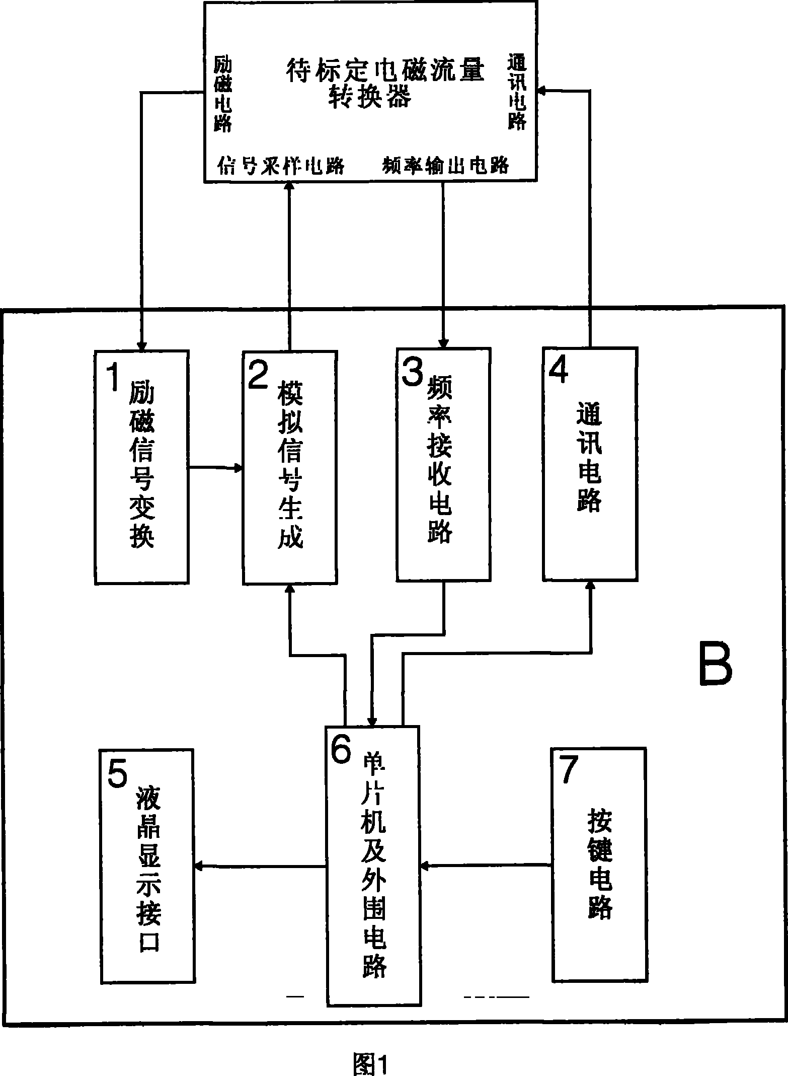
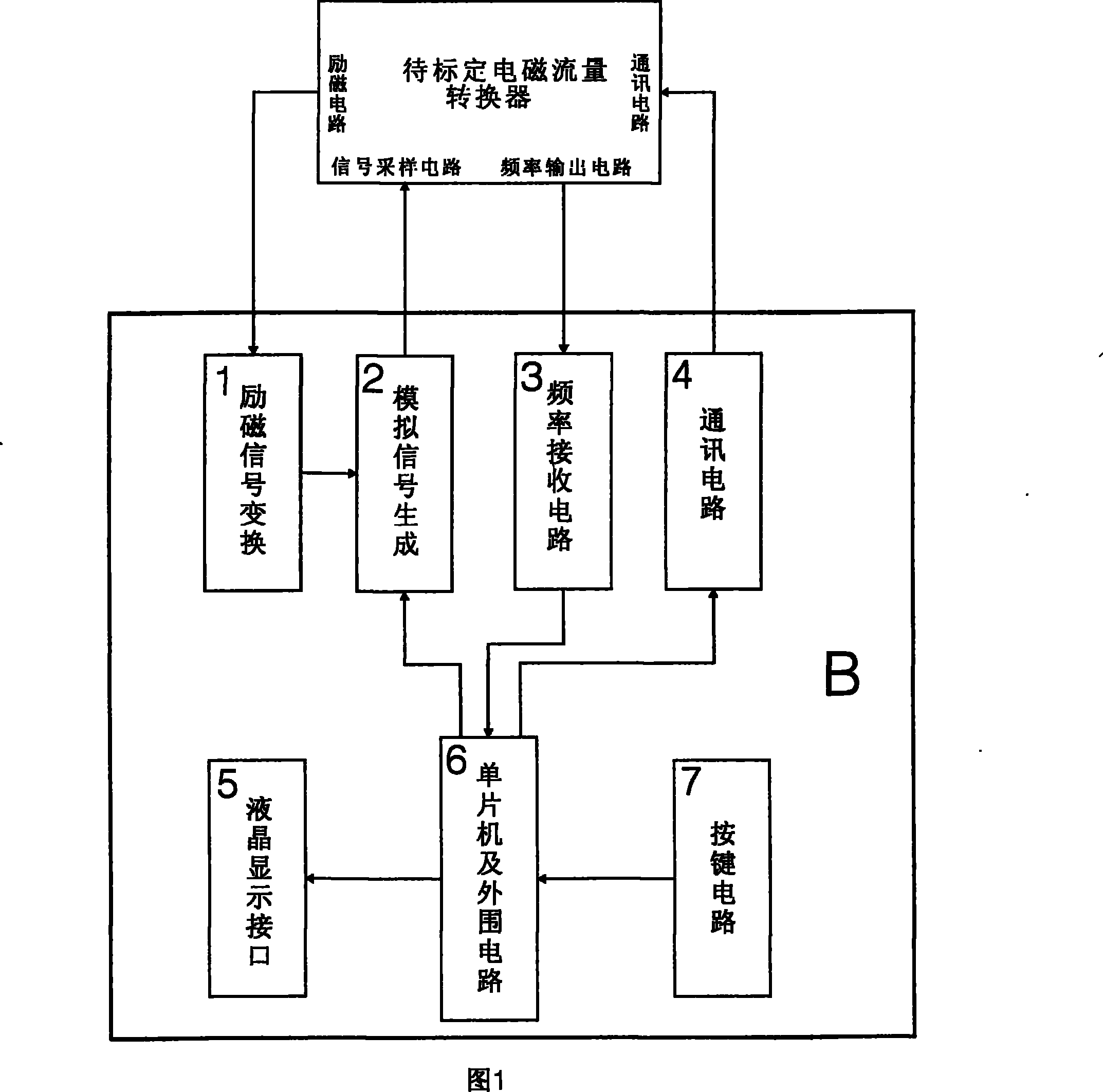
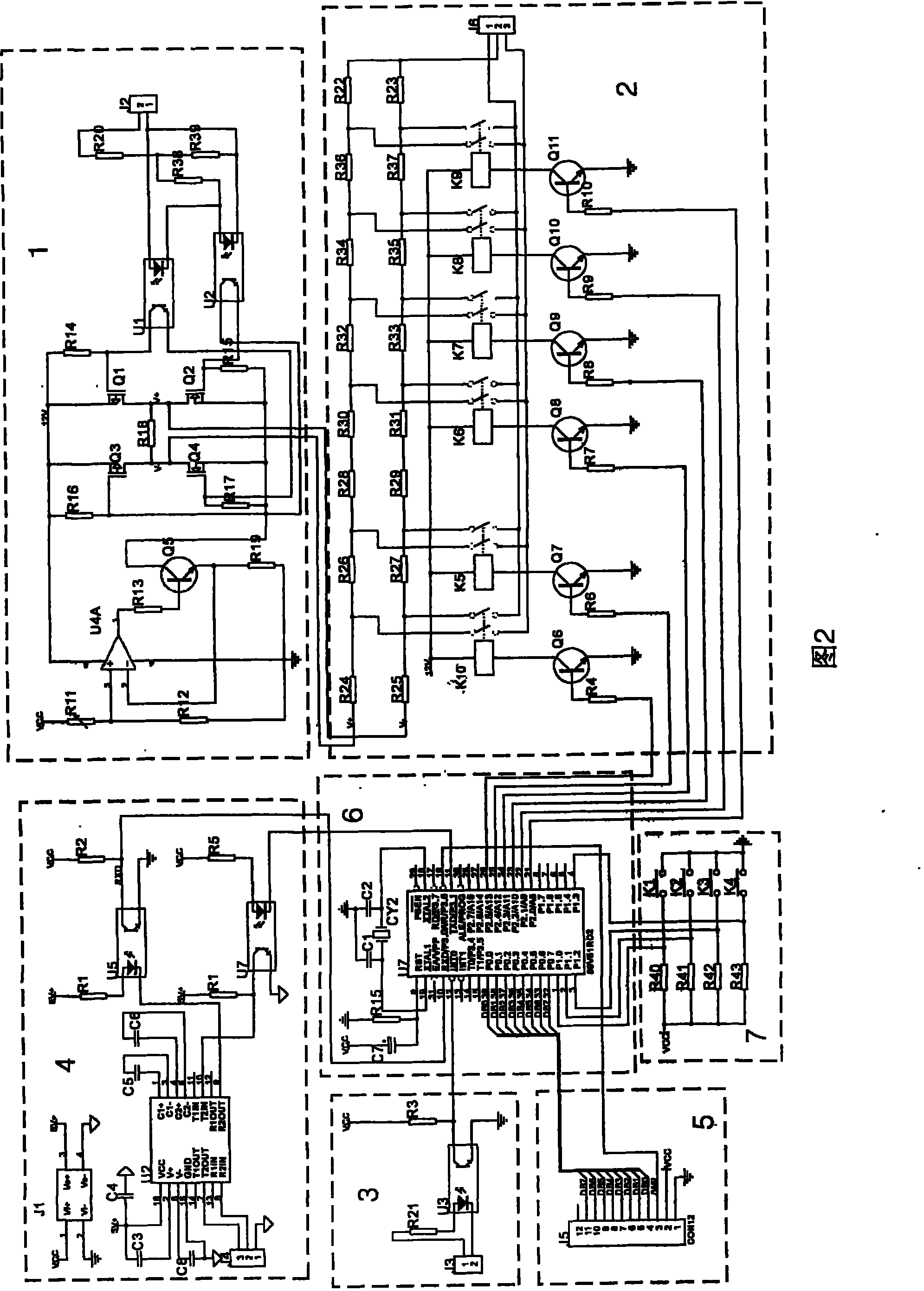
[0013] Fig. 1 is a block diagram of the circuit structure of the analog calibration device. As shown in Fig. 1, the technical scheme adopted by the analog calibration device of the electromagnetic flow converter of the present invention includes: the input is connected to the frequency output circuit of the electromagnetic flow converter to be calibrated, and the output is connected to The frequency receiving circuit 3 of the single-chip microcomputer and the peripheral circuit input interface; the input is connected to the single-chip microcomputer and the peripheral circuit output interface, and the output is connected to the communication circuit 4 of the electromagnetic flow converter to be calibrated; the input is connected to the liquid crysta...


PUM


Abstract

The invention relates to an analogue calibration device for an electromagnetic flow converter, solving the calibration problem of the electromagnetic flow converter. The technical proposal includes that the analogue calibration device comprises a frequency receiving circuit with the input end connected with the output end of the calibrated electromagnetic flow converter to be calibrated and the output end connected with the input interfaces of a single chip microcomputer and peripheral circuits; a communication circuit with the input end connected with signal interfaces of the single chip microcomputer and peripheral circuits and the output end connected with the calibrated electromagnetic flow meter converter; a LCD interface with the input end connected with the output ends of the single chip microcomputer and peripheral circuits; the single chip microcomputer and peripheral circuits with the input ends connected with the output ends of a keystroke circuit and the frequency receiving circuit and the output ends connected with an analogue signal generating circuit, the communication circuit and the LCD interface; an exciting signal transfer circuit with the input end connected with the output end of the exciting circuit of the electromagnetic flow converter to be calibrated; and an analogue signal generating circuit with the input end connected with the output ends of the exciting signal transfer circuit, the single chip microcomputer and peripheral circuits and the output end connected with the input end of the electromagnetic flow converter to be calibrated.

Description

Technical field: [0001] The invention relates to an electromagnetic flowmeter for measuring the volume flow of a conductive liquid continuously flowing through an instrument, in particular to an analog calibration device for an electromagnetic flow converter in the electromagnetic flowmeter, through which the analog calibration of the electromagnetic flow converter can be realized anytime and anywhere. technical background [0002] Electromagnetic flowmeter is a new type of flow measuring instrument developed rapidly with the development of electronics and communication technology in the 1960s. It is made according to Faraday's law of electromagnetic induction and is used to measure the volume flow of conductive fluids. Due to its unique advantages, it has been widely used in the measurement of various conductive liquids in industry. For example, measuring various acids, alkalis, salts and other corrosive liquids; various flammable and explosive media; various industrial sewa...

Claims


Application Information

Patent Timeline
Patent Type & Authority Patents(China)
IPC IPC(8): G01F25/00G01F1/58G01F15/00
CPCG01F1/60G01F25/10
Inventor 陈会庆张辉孙丽梅
Owner ZHONGHUAN TIG
Learn More