

Photocatalyst purification module and photocatalyst air purification device
A technology of air purification equipment and purification modules, applied in chemical instruments and methods, chemical/physical/physicochemical processes of energy application, separation of dispersed particles, etc., can solve the problem of uneven distribution of light intensity of light source 3 and poor photocatalytic effect , photocatalyst filter can not play a role and other problems
- Summary
- Abstract
- Description
- Claims
- Application Information
AI Technical Summary
Problems solved by technology
Method used
Image

Examples
Embodiment Construction
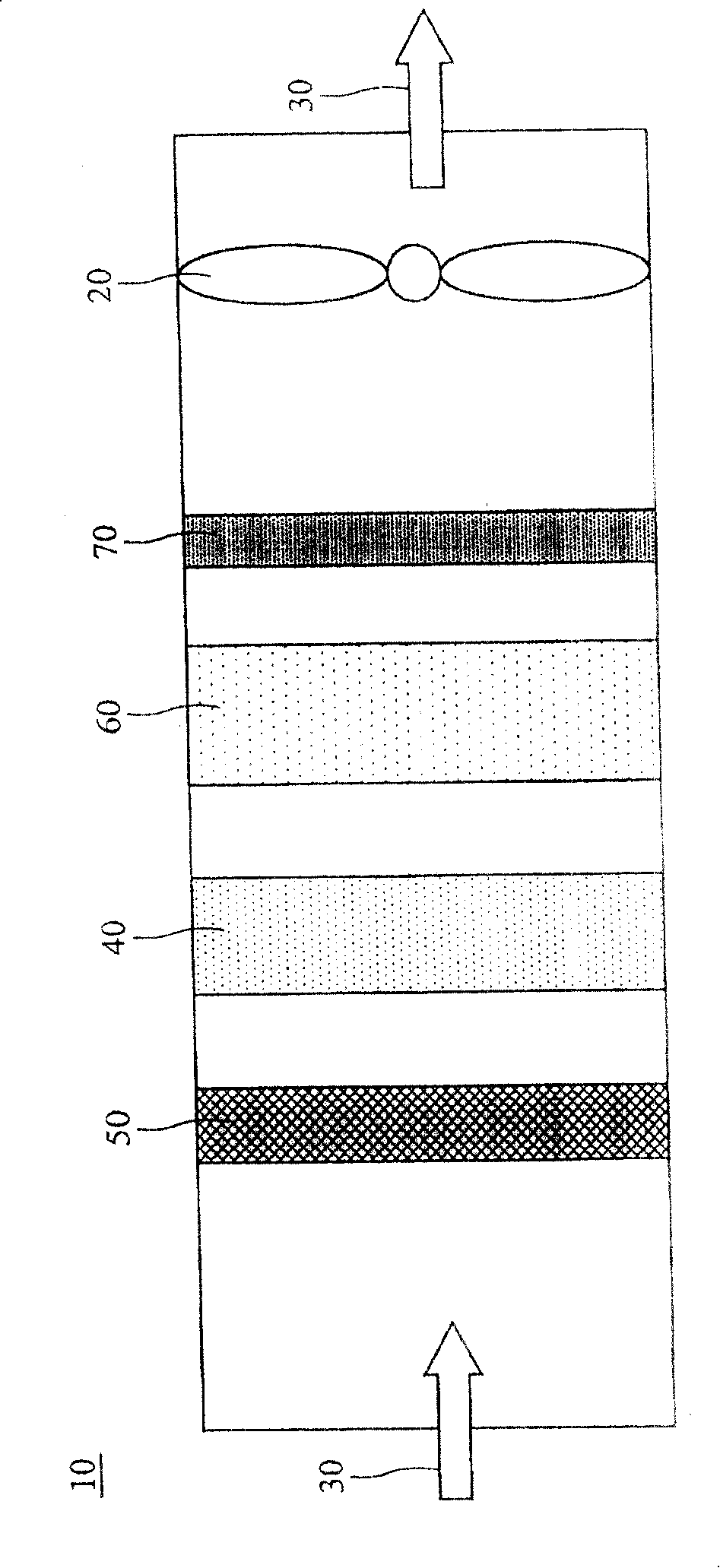
[0042] Photocatalyst air purification equipment of the present invention, for example figure 2 Applied in the air conditioning box 10, including the fan 20, the photocatalyst purification module 40, the primary filter 50, the air conditioning coil 60, and the heating device 70, wherein the fan 20 provides the airflow 30, and the airflow 30 first passes through the primary filter 50, and then passes through the photocatalyst The purification module 40 then flows through the air conditioning coil 60 , and the purified air is taken out by the heating device 70 and the fan 20 .
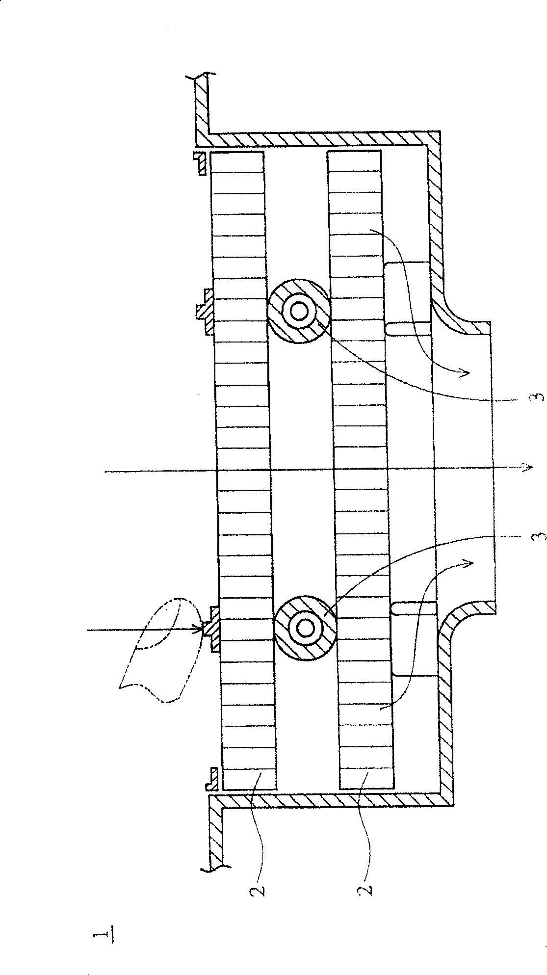
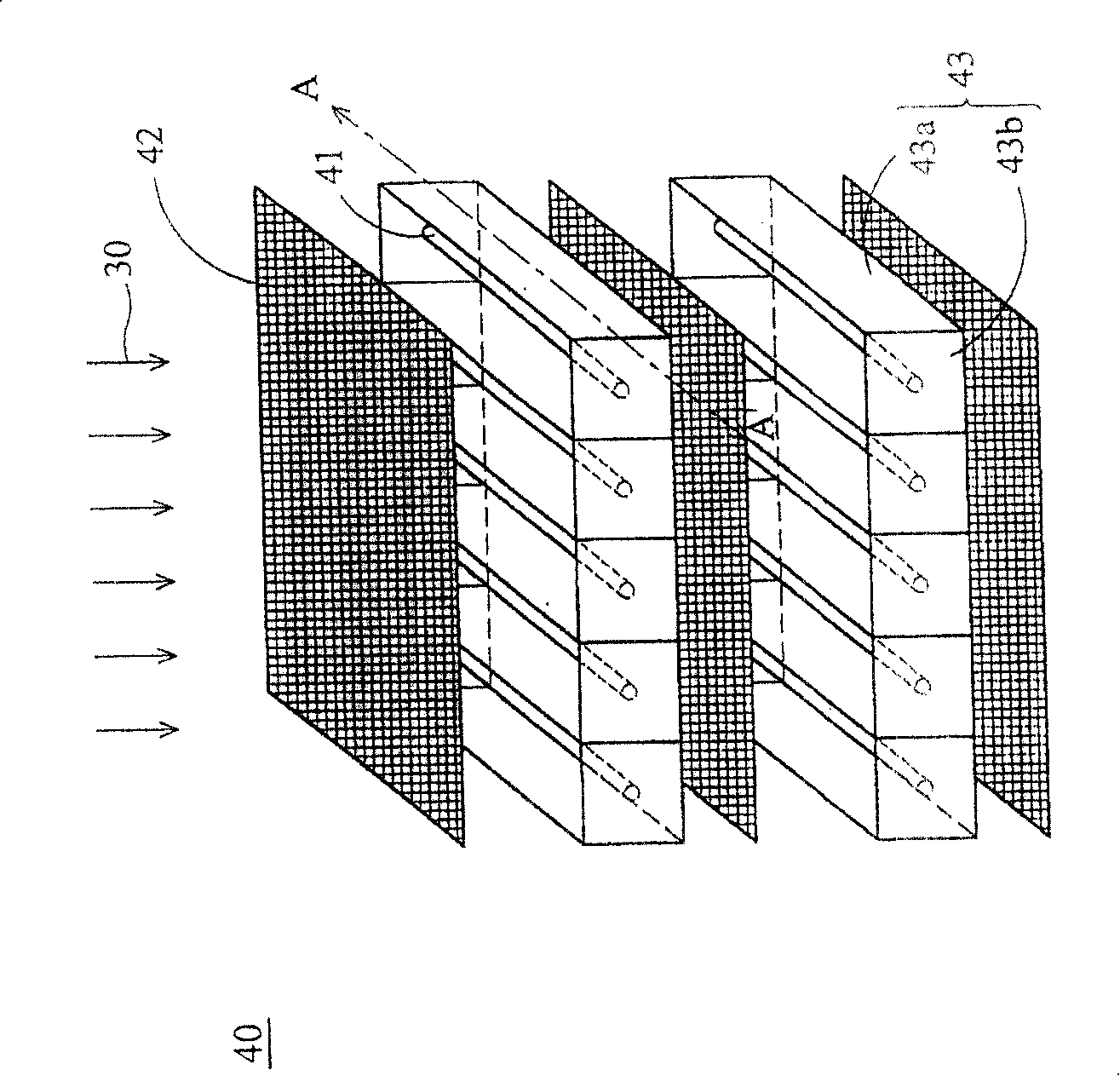
[0043] image 3 It is the photocatalyst purification module 40 of the present invention, including ten tubular light sources 41, three first photocatalyst filter screens 42, and a plurality of second photocatalyst filter screens 43, each of the first photocatalyst filter screens 42 is stacked up and down and parallel to each other The mode is arranged around the lamp tube-shaped light source 41, and the...
PUM
 Abstract
Description
Claims
Application Information