Lever clip mechanism

A technology of levers and substrates, applied in file folders, printing, binding, etc., can solve the problems of hindering the pressing down of the ring parts, the ring part cannot be fully closed, and the cover is damaged

Inactive Publication Date: 2008-07-23
LECO STATIONERY MFG CO LTD
View PDF0 Cites 2 Cited by
  • Summary
  • Abstract
  • Description
  • Claims
  • Application Information

AI Technical Summary

Problems solved by technology

When the roller presses against the ring part to close the lever clamp mechanism, the spring leaf at the lowest position on the underside of the ring part may come into contact with the cover, on the one hand hindering the downward pressure on the ring part so that the ring part of the lever clamp mechanism cannot be fully closed , on the other hand, a leaf spring in contact with the cover may cause the cover to break

Method used


Image

  • Lever clip mechanism
  • Lever clip mechanism
  • Lever clip mechanism

Examples


Embodiment Construction

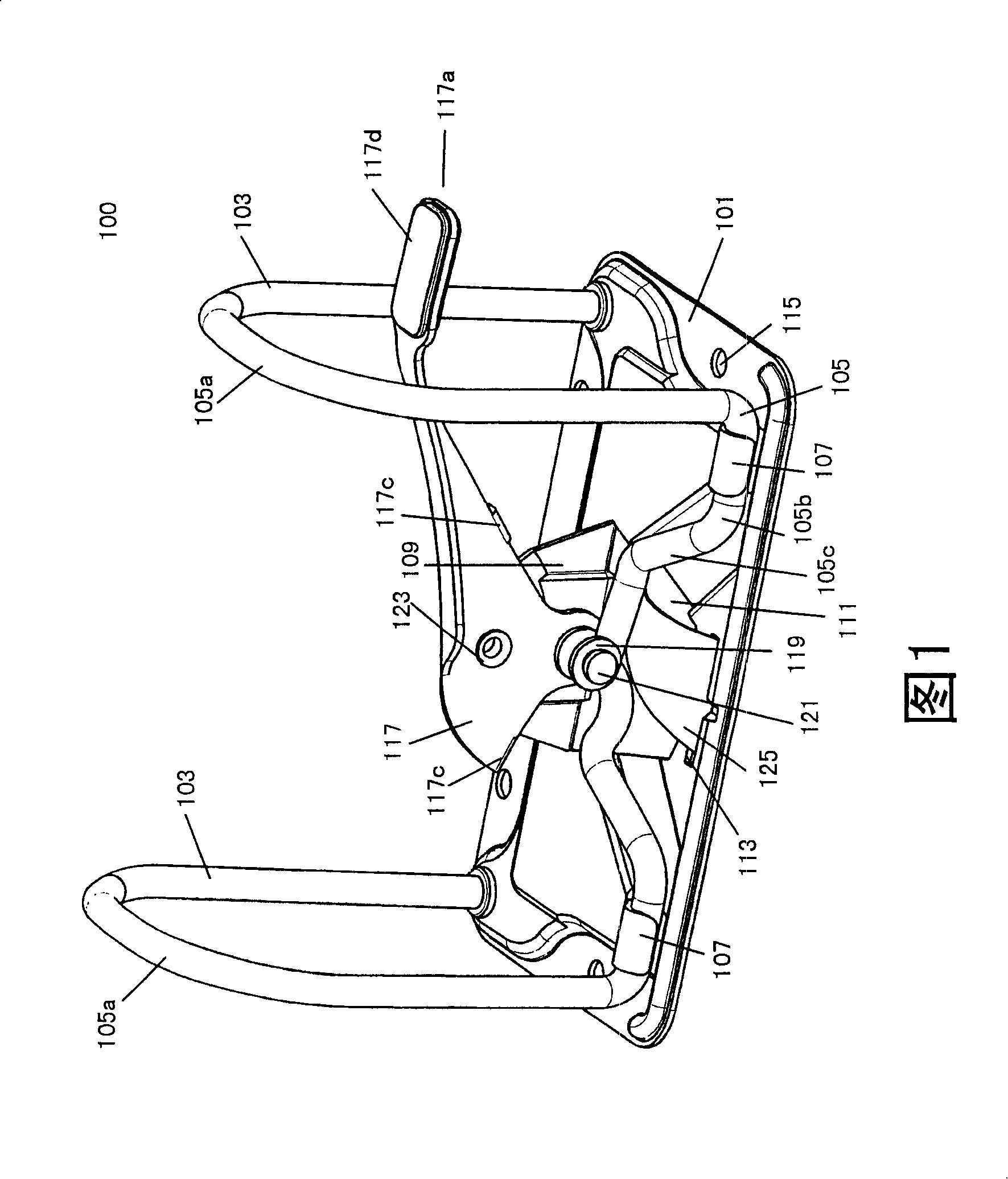
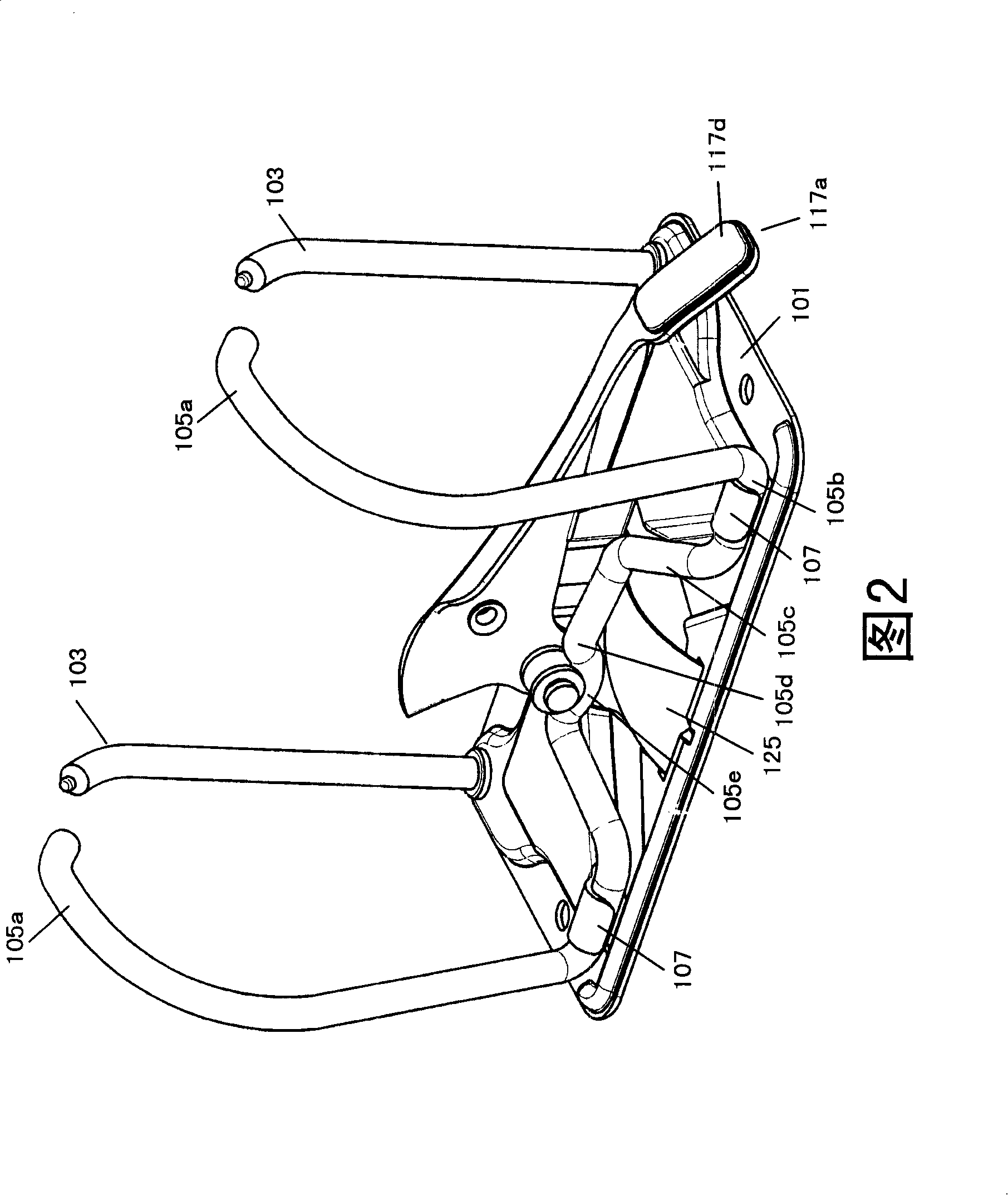
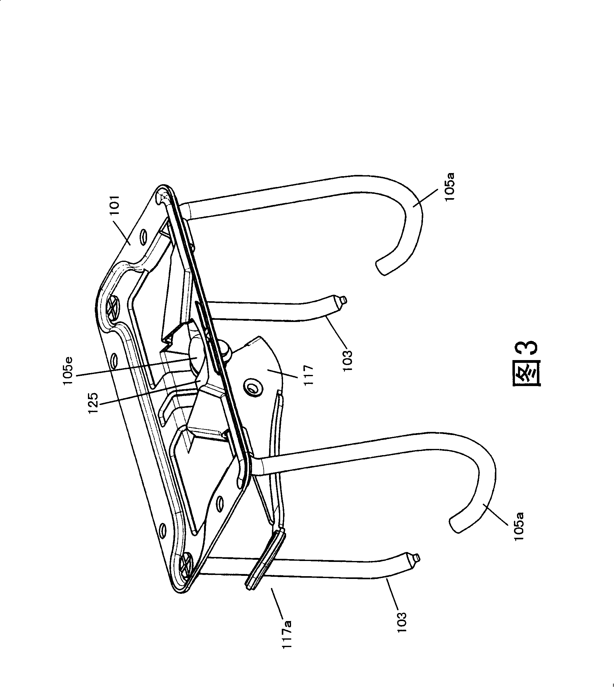
[0030] 1-4 show a lever clamp mechanism 100 according to a first embodiment of the present invention. The lever clamp mechanism 100 according to the first embodiment of the present invention includes a substantially flat base plate 101 . On one longitudinal side of the base plate 101 are fixedly mounted two mutually spaced apart and parallel first ring portions 103 extending substantially vertically upward from the base plate 101 and slightly bent at their free ends to form a bend. A ring member 105 is movably mounted on the other longitudinal side of the base plate 101 . The ring member 105 includes two second ring parts 105a spaced apart from each other and parallel to each other, and a connecting part 105b connecting the two second ring parts 105a into one body. Each second ring portion 105a is respectively formed with a bent portion at its free end, so that the two second ring portions 105a of the ring member 105 can cooperate with the corresponding opposite first ring p...


PUM


Abstract

A lever clamping mechanism comprises a base plate, two first ring parts which are fixedly arranged on the base plate and are spaced and parallel to each other, a ring piece which is movably arranged on the base plate and comprises two second ring parts which are spaced and parallel to each other; wherein, the two first ring parts are respectively arranged correspondingly to the two second ring parts, which ensures the first ring part and the second ring part which are opposite to each other to form a close ring when the lever clamping mechanism is closed; one end is arranged on the base plate and the other end leans on an elastic piece of the ring part; the invention also comprises a bulging part which is protuberant upwards from the base plate, a lever which is provided with a leaning part and is rotatablely arranged on the bulging part to lead the leaning part to be contacted with the ring part; wherein, the end of the electric piece which leans on the ring part is higher than the lowest part of the ring part. When the lever clamping mechanism of the invention is closed, the electric piece can not be contacted with a piece of wrappage, which ensures the ring part of the lever clamping mechanism to be closed completely without damaging the wrappage.

Description

technical field [0001] The invention relates to a lever clamp mechanism. Background technique [0002] The lever clip mechanism is a type of stationery widely used to store paper sheets such as loose-leaf papers. The prior art lever clamp mechanism comprises a substantially flat base plate; two first ring portions spaced apart from each other and fixedly mounted at one end thereof to one longitudinal side of the base plate, the two first ring portions extending substantially perpendicularly from the base plate extending upward and slightly bent at its other end to form a bend; two second ring portions spaced apart from each other and movably mounted at one end to the other longitudinal side of the base plate, the two second ring portions extending from the base plate Extends substantially vertically upwards and also forms an additional bend at its other end so as to cooperate with the bend at the other end of the two first ring portions to form a closed loop when the lever ...

Claims


Application Information

Patent Timeline
Patent Type & Authority Applications(China)
IPC IPC(8): B42F3/04B42F13/24
CPCB42F13/24
Inventor 杜振源郑洪如邓熙涛
Owner LECO STATIONERY MFG CO LTD
Why Eureka
Try Eureka