
Hot-water air conditioner and control method

A control method and air conditioner technology, which is applied to heating methods, air conditioning systems, heating and ventilation control systems, etc., can solve problems such as damaged compressors, insufficient refrigerant, and reduced work efficiency, so as to facilitate mass production, popularization and application, Increased hot water heating function and remarkable energy saving effect

Inactive Publication Date: 2008-07-23
奉政一
View PDF0 Cites 3 Cited by
  • Summary
  • Abstract
  • Description
  • Claims
  • Application Information

AI Technical Summary

Problems solved by technology

[0002] The current air conditioners discharge the heat generated by indoor cooling to the outside, resulting in double waste of energy expenditure
Although there are many hot water air conditioner patent applications similar to the present invention, such as patent numbers: 200510046533.4, 200520091547.3, in practical application, it is felt that when the water in the water tank has not been heated, the refrigerant in the entire system will be concentrated in the water condenser , resulting in low cooling and heating efficiency. If the water in the water tank is not used after being heated, and the cooling air needs to be continued, the refrigerant in the entire system will be concentrated in the internal and external heat exchanger units of the air conditioner. At this time, only cooling air or single system When the warm air is working, there will be too much refrigerant in the internal and external heat exchanger units, and the working efficiency will be greatly reduced. In severe cases, liquid shock reaction will occur and the compressor will be damaged; if the refrigerant charge of the entire system is reduced, the hot water air conditioner will When cooling / hot water or heat pump heating water level is working, there will be insufficient refrigerant, and the compressor will be short of oil and shorten the service life.

Method used


Image

  • Hot-water air conditioner and control method
  • Hot-water air conditioner and control method
  • Hot-water air conditioner and control method

Examples


Embodiment 1

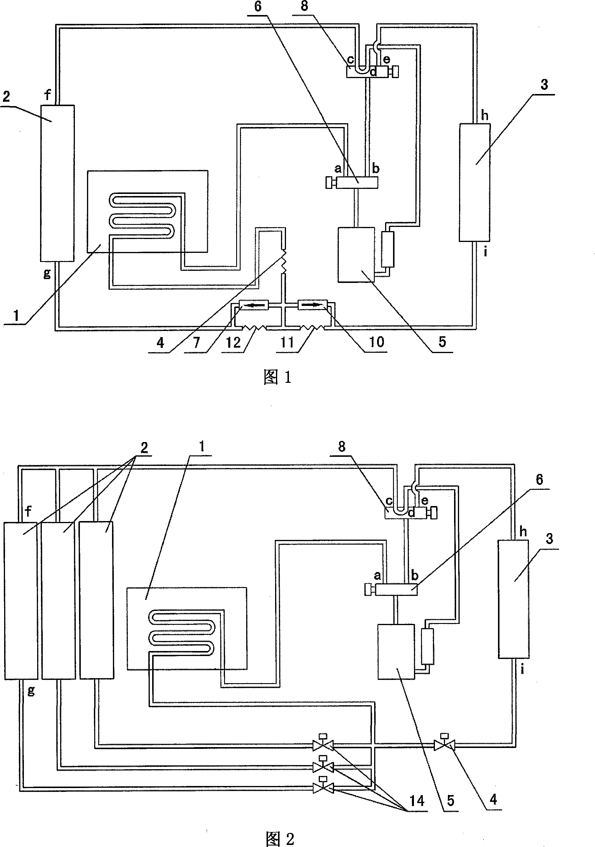
[0039] Embodiment 1 As shown in Figure 1, it includes: a water condenser 1, an inner heat exchanger unit 2, an outer heat exchanger unit 3, a throttling component 4, a compressor 5, a hot water switching valve 6, and a refrigeration check valve 7. The heating and cooling reversing valve 8, the control system 9, the heating one-way valve 10, the cooling capillary 11, the heating capillary 12 and the connecting pipeline; in the hot water air conditioning unit, the outlet of the compressor 5 is connected to the hot water switching valve The inlet of 6, the a port of the hot water switching valve 6 is connected to the inlet of the water condenser 1, the outlet of the water condenser 1 is connected to the inlet of the throttling component 4, the b port of the hot water switching valve 6 is connected to the inlet of the cooling and heating reversing valve 8, The d port of the cooling and heating reversing valve 8 is connected to the air return port of the compressor 5, the c port of ...

Embodiment 2

[0045] Embodiment 2, as shown in Figure 2, includes: a water condenser 1, an inner heat exchanger unit 2, an outer heat exchanger unit 3, a throttling component 4, a compressor 5, a hot water switching valve 6, and a heating and cooling reversing Valve 8, control system 9, cooling and heating electronic expansion valve 14 and connecting pipelines; in the hot water air conditioning unit, the outlet of compressor 5 is connected to the inlet of hot water switching valve 6, and the a port of hot water switching valve 6 is connected to water condensation The inlet of the device 1, the b port of the hot water switching valve 6 is connected to the inlet of the cooling and heating reversing valve 8, the d port of the cooling and heating reversing valve 8 is connected to the air return port of the compressor 5, and the e port of the cooling and heating reversing valve 8 is connected to the external heat exchanger The h port of unit 3, the i port of the external heat exchanger unit 3 are...

Embodiment 3

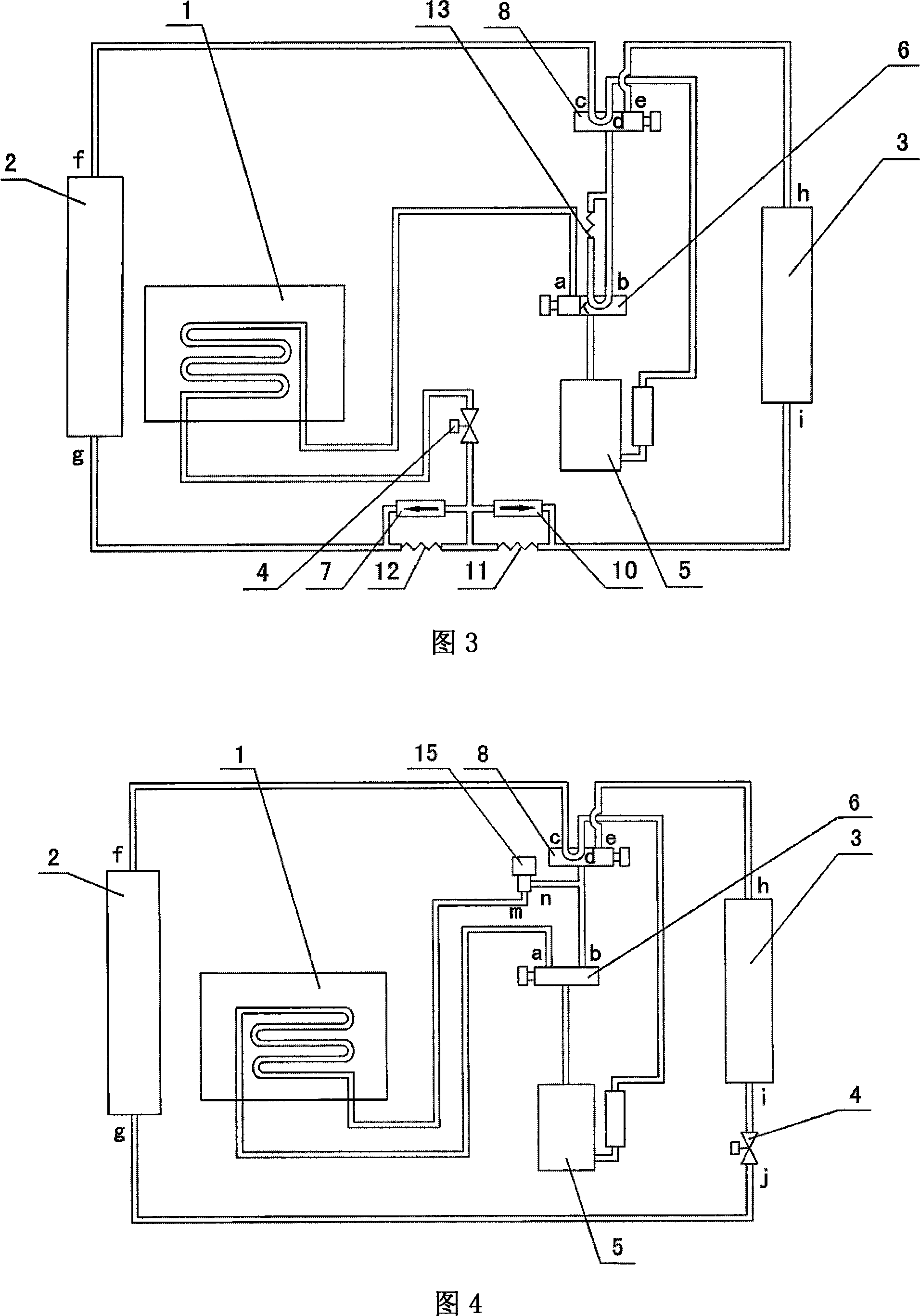
[0051]Embodiment 3, as shown in Figure 3, includes: a water condenser 1, an inner heat exchanger unit 2, an outer heat exchanger unit 3, a throttling component 4, a compressor 5, a hot water switching valve 6, and a cooling one-way Valve 7, heating and cooling reversing valve 8, control system 9, heating check valve 10, cooling capillary 11, heating capillary 12, throttling capillary 13 and connecting pipelines; The outlet is connected to the inlet of the hot water switching valve 6, the a port of the hot water switching valve 6 is connected to the inlet of the water condenser 1, the k port of the hot water switching valve 6 is connected to the throttling capillary 13, and the b port of the hot water switching valve 6 is connected to the The inlet of the cooling and heating reversing valve 8 is connected with the other port of the throttling capillary 13, the outlet of the water condenser 1 is connected to the inlet of the throttling part 4, the d port of the cooling and heatin...


PUM


Abstract

The invention relates to an air-conditioner and the control method, more exactly, a hot water air-conditioner and the control method, which belongs to the technical field of air-conditioning technologies and is for the purpose to provide a solution to the problem of unbalance configuration of air-conditioning refrigerant; wherein the control method is to switch among different working states of the hot water air-conditioner by adjusting working refrigerant amount between the internal / external heat exchange units and the water-cooling condenser; the hot water air-conditioner comprises internal / external heat exchange units, a water-cooling condenser and a compressor, wherein a solenoid valve is provided between the water-cooling condenser and the high-voltage output pipeline of the compressor, or a solenoid valve is provided between the low-voltage input tube of the compressor and the water-cooling condenser, or a hot water changeover valve is provided between the high-voltage output pipeline of the compressor and the water-cooling condenser, or an electronic expansion valve is provided between the internal / external heat exchange units. The air-conditioner and the control method has the advantages of balanced and reasonable configuration of refrigerant, striking energy-saving result, long service life for the complete machine and low production cost.

Description

technical field [0001] The invention relates to a hot water air conditioner, in particular to a method for controlling the hot water air conditioner. Background technique [0002] The current air conditioners all discharge the heat generated by indoor cooling to the outside, resulting in double waste of energy expenditure. Although there are many hot water air conditioner patent applications similar to the present invention, such as patent numbers: 200510046533.4, 200520091547.3, in practical application, it is felt that when the water in the water tank has not been heated, the refrigerant in the entire system will be concentrated in the water condenser , resulting in low cooling and heating efficiency. If the water in the water tank is not used after being heated, and the cooling air needs to be continued, the refrigerant in the entire system will be concentrated in the internal and external heat exchanger units of the air conditioner. At this time, only cooling air or sing...

Claims


Application Information

Patent Timeline
IPC IPC(8): F24F11/00F25B1/00
CPCF24F5/0096
Inventor 奉政一
Owner 奉政一
Learn More