Integrated wingtip extensions for jet transport aircraft and other types of aircraft

A technology for extensions and aircraft, applied in the field of wings, capable of solving the problem that the final shape of the airfoil of the improved wing assembly 200 is not optimal, etc.

Inactive Publication Date: 2008-07-23
THE BOEING CO
View PDF0 Cites 26 Cited by
  • Summary
  • Abstract
  • Description
  • Claims
  • Application Information

AI Technical Summary

Problems solved by technology

However, one disadvantage of this approach is that the final airfoil shape of

Method used


Image

  • Integrated wingtip extensions for jet transport aircraft and other types of aircraft
  • Integrated wingtip extensions for jet transport aircraft and other types of aircraft
  • Integrated wingtip extensions for jet transport aircraft and other types of aircraft

Examples


Embodiment Construction

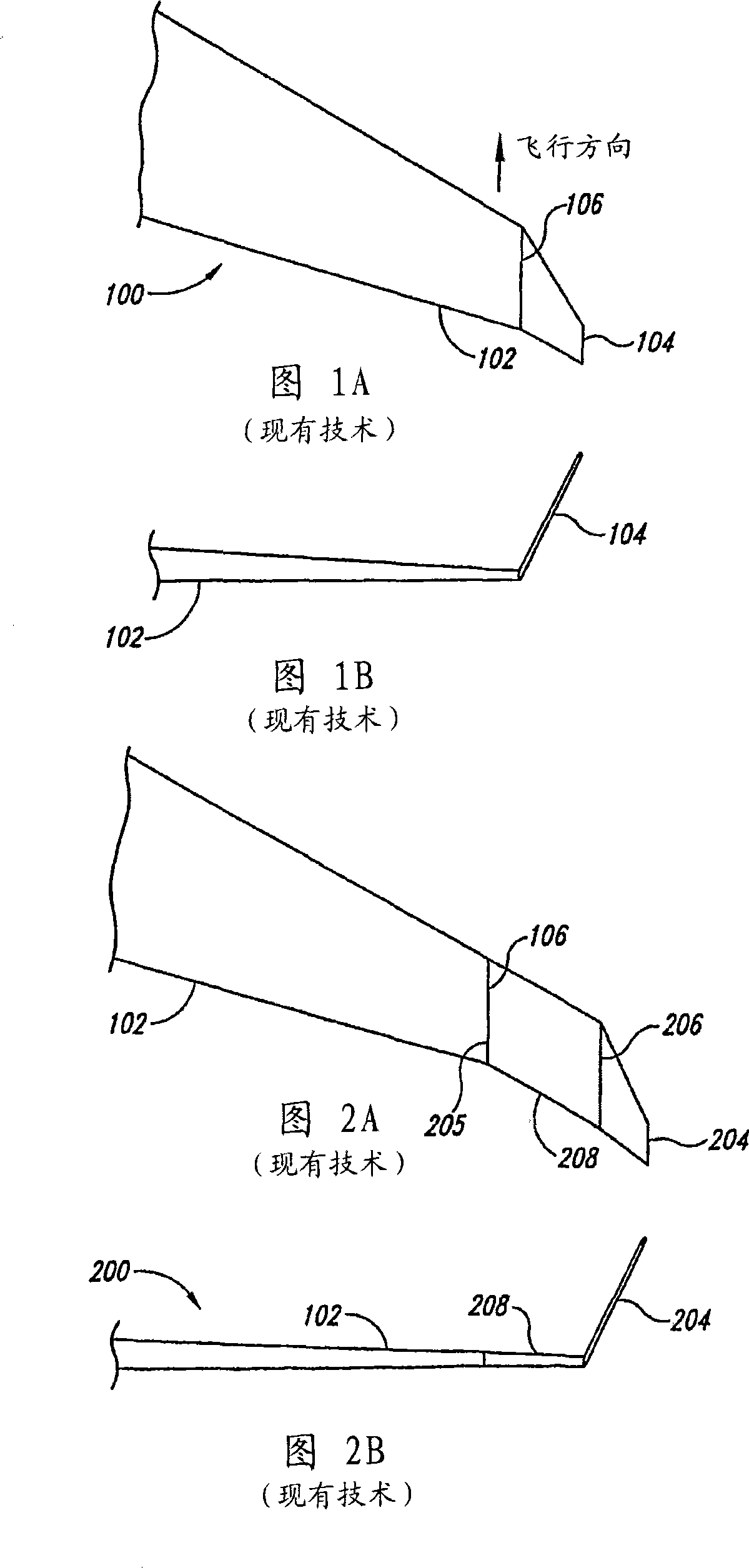
[0020] The following publications describe systems and methods for increasing wing area on various types of baseline aircraft. In the following description, certain details are set forth in order to provide a thorough understanding of various embodiments of the invention. However, other details describing structures and systems that are well known and often associated with aircraft, wings and / or airfoils are not described below in order to avoid unnecessarily obscuring the various embodiments of the present invention.

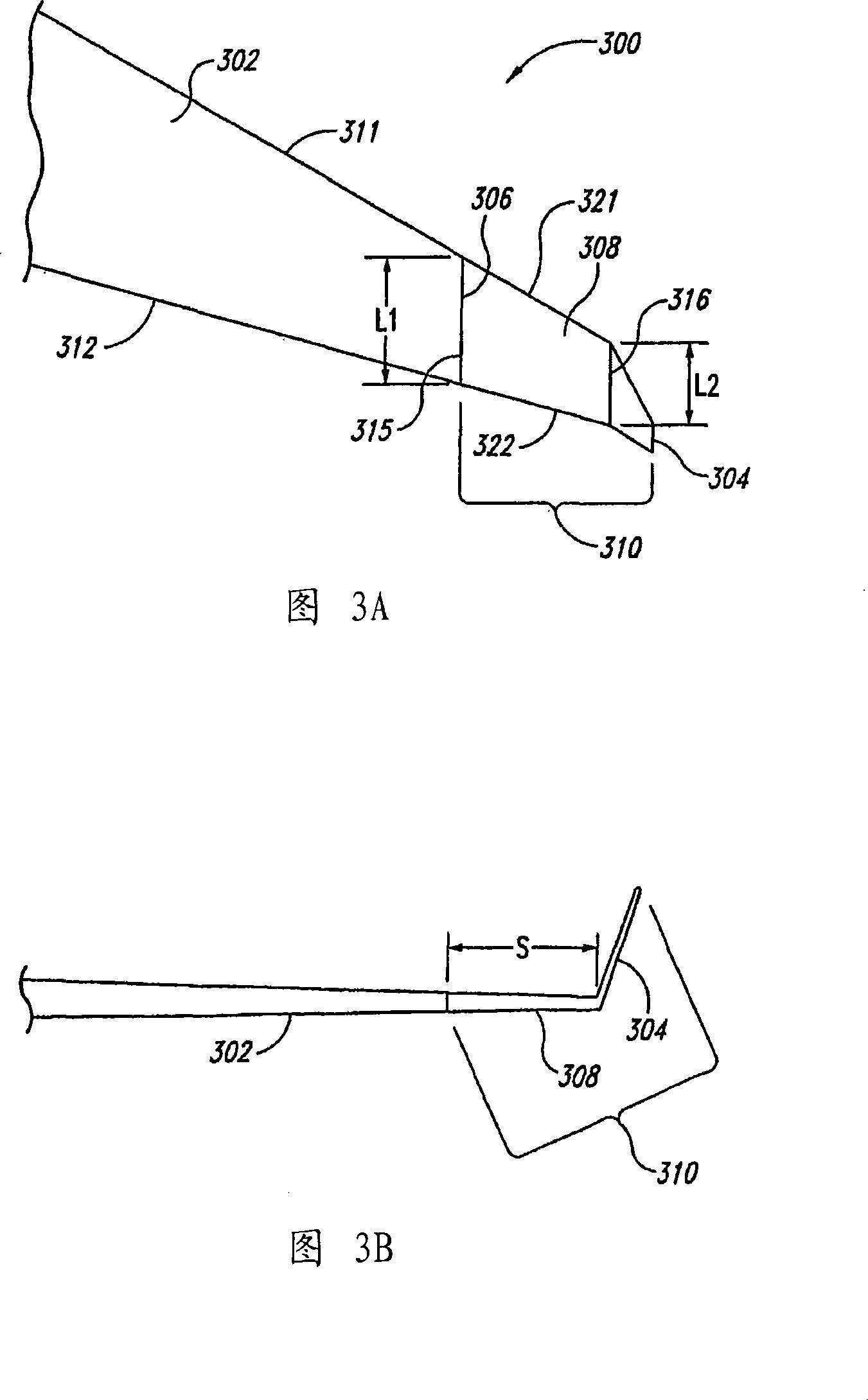
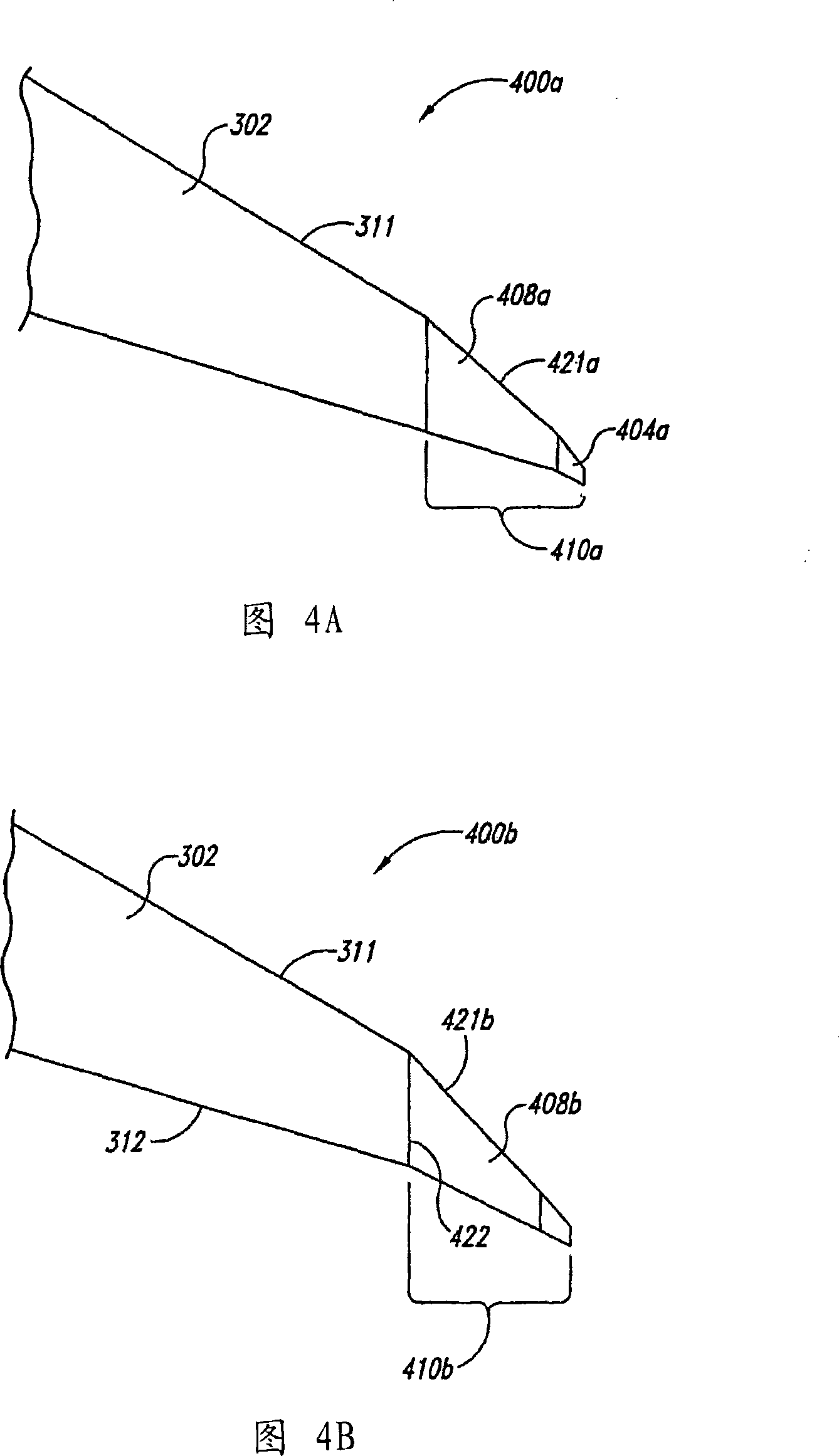
[0021] Many of the details, dimensions, angles and other features shown in the drawings are illustrative of specific embodiments of the invention. Accordingly, other embodiments may have other details, dimensions, angles, and other features without departing from the spirit or scope of the present invention. Moreover, further embodiments of the invention may be practiced without several of the details described below.

[0022] In the figures, identical refere...


PUM


Abstract

Methods and systems for efficiently increasing the wing area of an aircraft are disclosed herein. An integrated wingtip extension (310) configured in accordance with one embodiment of the invention includes a tapered wing section and a winglet (304). The tapered wing section (308) includes an inboard end portion (306) having a first chord length (L1) and an outboard end portion (306) having a second chord length (L2) that is less than the first chord length (L1). The winglet (304) is fixedly attached to the outboard end portion (316). The inboard end portion (306) is configured to be fixedly attached to a tip portion of an aircraft wing (302). In one embodiment, the tapered wing section (308) and the winglet (304) can be integrally formed from composite materials.

Description

technical field [0001] The following disclosure relates generally to airfoils, and more specifically to wing tip extensions of airfoils. Background technique [0002] Aircraft manufacturers often develop families of aircraft in which subsequent models of the aircraft are capable of carrying more passengers and / or cargo than earlier models. Increasing the carrying capacity of passengers and / or cargo is generally achieved by increasing the area of ​​the fuselage and / or wings. One prior art method for increasing airfoil area is illustrated in Figures 1A-2B. [0003] FIG. 1A is a top view of a baseline wing assembly 100 arranged according to the prior art, and FIG. 1B is a rear view looking forward at the baseline wing assembly 100 . Referring concurrently to FIGS. 1A and 1B , the baseline wing assembly 100 includes a baseline wing 102 and an airfoil 104 . The airfoil 104 is fixedly connected to the airfoil end of the baseline airfoil 102 . Although the chord length of the w...

Claims


Application Information

Patent Timeline
IPC IPC(8): B64C23/06B64C3/10
CPCY02T50/164B64C23/065B64C23/069Y02T50/10
Inventor 维克托·K·斯图尔
Owner THE BOEING CO
Why Eureka
Try Eureka