Eureka AIR delivers breakthrough ideas for toughest innovation challenges, trusted by R&D personnel around the world.

Mapping method and device of virtual LAN

A technology of virtual local area network and mapping method, which is applied in the field of VLAN mapping to achieve the effect of improving processing capacity and saving ACL resources

Active Publication Date: 2008-08-06
NEW H3C TECH CO LTD
View PDF0 Cites 24 Cited by
  • Summary
  • Abstract
  • Description
  • Claims
  • Application Information

AI Technical Summary

Problems solved by technology

[0004] In the prior art, in order to realize VLAN mapping, ACL (Access Control List, Access Control List) is usually used to modify the VLAN tag (VLAN identification) in the upstream message from the user-side VLAN to the network-side VLAN. The packet also uses ACL to modify the VLAN tag in the packet from the network-side VLAN to the user-side VLAN, which requires a large number of ACLs

Method used


Image

  • Mapping method and device of virtual LAN
  • Mapping method and device of virtual LAN

Examples


Embodiment Construction

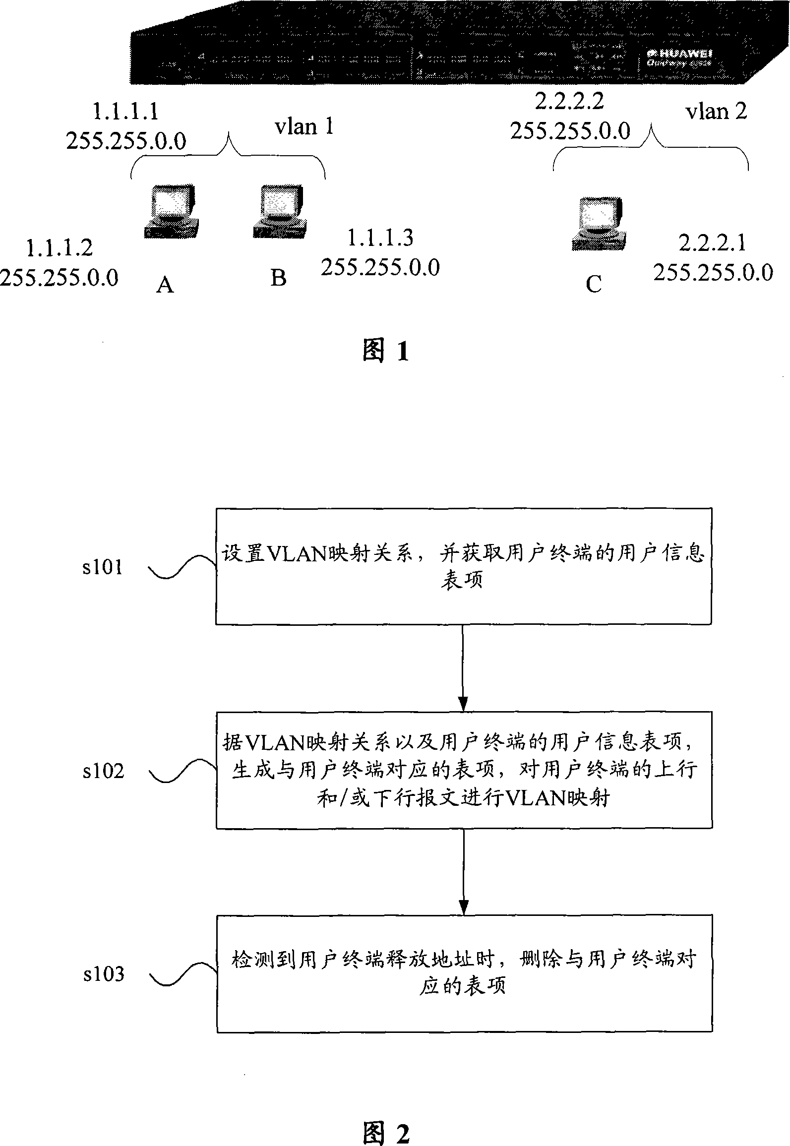
[0063] In the following description of the present invention, VLANs that need to be mapped are classified, specifically including user-side VLANs and network-side VLANs. Wherein, the user side VLAN refers to a VLAN located at the access side and needs to be mapped; the network side VLAN refers to a network side VLAN. Specifically, after the upstream message from the user side VLAN is processed by VLAN mapping, the VLAN tag carried in the message is converted from the user side VLAN to the network side VLAN; after the downstream message from the network side VLAN is processed by VLAN mapping, The VLAN tag carried in the message is converted from the network-side VLAN to the corresponding user-side VLAN.

[0064] The mapping method of a kind of VLAN is provided among the present invention, as shown in Figure 2, comprises the following steps:

[0065] Step s101, setting the VLAN mapping relationship, and obtaining the user information entry of the user terminal.

[0066] Specif...


PUM


Abstract

The invention discloses a mapping method and mapping equipment for a virtual local area network (VLAN). The mapping method of the VLAN comprises the following steps that: a VLAN mapping relation is set, and a user information list item of a user terminal is obtained; a list item corresponding to the user terminal is generated according to the VLAN mapping relation and the user information list item of the user terminal; VLAN mapping is made to an up message and / or down message of the user terminal according to the generated list item. By using the method and the equipment provided by the invention, the information of the user terminal is obtained and the corresponding list item is generated; the generated list item is used to realize the dynamic management of the VLAN mapping without a large quantity of ACLs on network equipment, thereby saving the ACL resource of the network equipment and improving the processing ability of the network equipment.

Description

technical field [0001] The invention relates to the technical field of communications, in particular to a VLAN (Virtual Local Area Network) mapping method and device. Background technique [0002] In the prior art, in order to improve the security and reliability of the network, a VLAN technology is proposed. The same physical LAN can be divided into multiple VLANs. VLANs cannot be accessed directly, but can only be accessed through routing devices. For example, in the situation shown in FIG. 1 , direct Layer 2 communication cannot be performed between VLAN1 and VLAN2, and each VLAN interface must be configured with an IP address and a corresponding MAC (Medium Access Control, Media Access Control) address. Only after static configuration or dynamic learning of ARP (Address Resolution Protocol, address resolution protocol) entries and routing entries, communication between VLANs can be performed. [0003] In the current network, an L3 switch (L3Switch) is usually used as a...

Claims


Application Information

Patent Timeline
Patent Type & Authority Applications(China)
IPC IPC(8): H04L12/46H04L12/56H04L45/74
Inventor 郑上闽杜澎李爱国
Owner NEW H3C TECH CO LTD
Why Eureka
Eureka Blog
Learn More